








.svg)

Part 1: Introduction to Workholding
“Time is money.”
“If you’re not making chips you’re not making money.”
Everyone in the machining business has heard these two sayings. The first one urges us to optimize productivity and profitability by reducing total cycle time for machining operations. The second reminds us that underutilized machines are a waste of capital resources. It also highlights the fact that cycle time for any component being produced is composed of the time when the machine is actively removing material from the workpiece, or making chips, and the time spent on all of the other activities that must also be performed. Above all, it urges us to minimize the non-chipmaking component of cycle time to improve profitability.
The choice of fixtures and devices to hold the workpiece during machining can have a large effect on cycle time and profitability of machining operations. In this series, we will explore how the choice of workholding systems impacts both the economics and the physics of the machining process.
Economics is about time and money, and it prompts us to minimize the time spent in all phases of the machining business to increase profitability. Essentially, it tells us what we want to do. The economics of the machining business pressures us to constantly improve the productivity of our operations. To do this, we must make optimal use of our shop floor personnel and of the machine tools in our inventory. This can take the form of effective scheduling to minimize idle time, as well as minimizing cycle time for individual pieces.
Unfortunately, machine tools and machining processes, 3PART 1 including workholding and fixturing, are governed by the laws of physics, which place constraints on what we are actually able to do. The physical properties of the machine tool and workholding system include such things as spindle torque and power, number and arrangement of axes, axis velocity and acceleration, workspace size and shape, and stiffness and damping. The selection of tooling, machining parameters, and tool paths combine with the physical properties of the machine tool and workholding system to determine the resulting cutting forces, deflections and vibrations, and thermal distortions of the system; and ultimately the accuracy and surface finish of the resulting product.
The economics and the physics of machining strongly interact, and are often at odds. Finding the sweet spot for operations requires a good understanding of both. We will see in this series of articles that the selection of workholding systems plays an important role in both the economics and physics of machining.
The goals of this series of articles are to provide the reader with:
- An understanding of basic machining physics and how this constrains what is possible in machining operations
- An understanding of the range of options available for fixturing and workholding, including tombstones, fixturing plates, and clamping systems
- An understanding of how selection of workholding system components, including materials, affects both the physics and economics of machining operations
In this series of articles we will present a comprehensive guide for stationary workholding and fixturing to aid the machining community in optimizing their operations.
Part 2: The Economics of Workholding
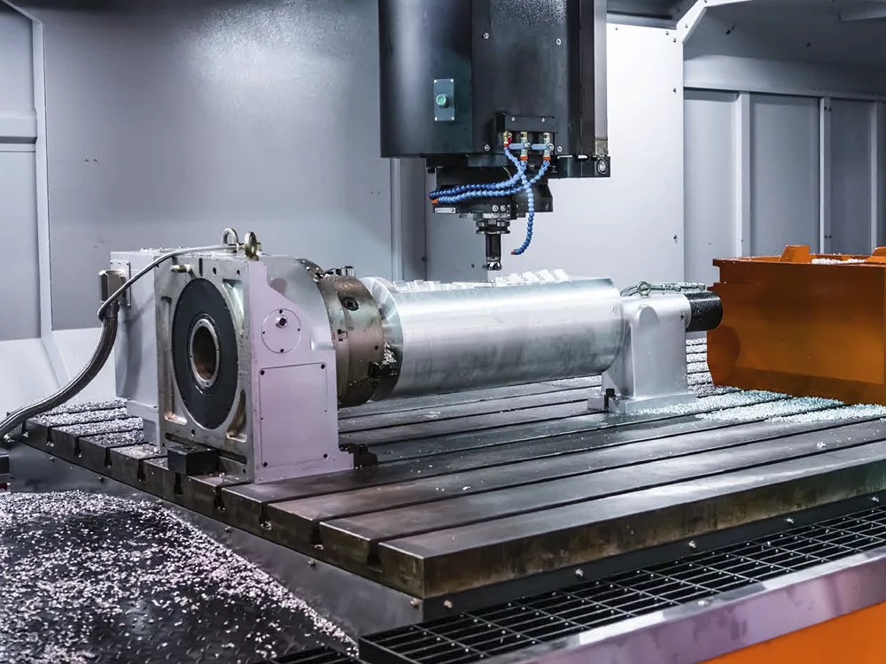
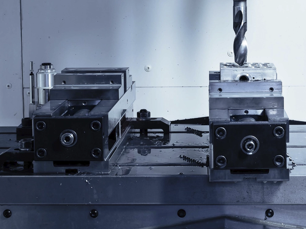
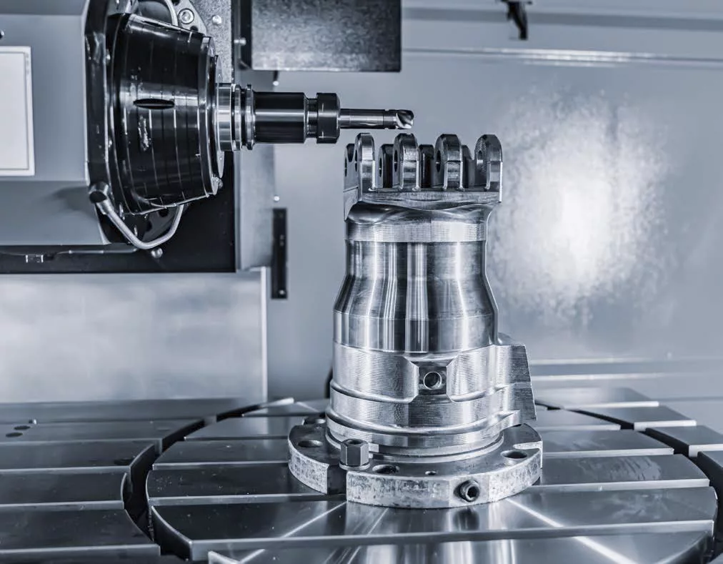
Machining is a subtractive process in which material is removed from an oversized workpiece until the final part geometry is achieved. In traditional machining, a sharpedged tool moves through the workpiece to form small chips. This chipmaking process results in forces being applied to the workpiece that are sometimes quite large. Therefore, all machining operations require a system to hold the workpiece securely enough to resist these machining forces. In many shops, this takes the form of a manual vise that is permanently mounted to the machine worktable. In this article we will examine how the choice of the workholding system can dramatically impact the economics of machining operations.
One of the biggest contributors determining the cost to produce a machined part is the cycle time, or the total elapsed time between the loading of a raw workpiece into a machine and the removal of a finished part. The total cycle time is generally composed of time spent making chips, or actually cutting material from the workpiece, and other, nonchipmaking, activities. The familiar saying, “if you’re not making chips you’re not making money”, reminds us that minimization of the nonchipmaking portion of the cycle time is critical to the operation’s profitability. Of course it’s equally important to minimize the chipmaking portion of the cycle time through optimal selection of tooling, tool paths, and machining parameters. That topic will be covered in a later article.
The major non-chipmaking contributors to cycle time are:
- Part loading and unloading
- Machine start and stop
- Door opening and closing
- Blowing chips and coolant away from the finished parts Clamping and unclamping of the part(s), including locating and re-stowing of any required tools
- Cleaning of the machine workspace and fixture to prepare it to accept the new workpiece
- Tool changes
- Part touch-off if required
- In-process inspections as needed
- Periodic machine cleaning and maintenance, apportioned to the number of parts produced between these activities
- Loading and setting of cutting tools, allotted proportionately on the number of parts produced between these activities
One of the most important factors influencing the selection of workholding systems is the total production volume, or the number of identical parts that are going to be made; and the batch size, or number of identical parts that will be made in a single setup and run. For one-off parts or prototypes, all contributors must be included in the cycle time for each part. In cases of large production runs and continuous production, it can make sense to design and build custom, automated workholding systems dedicated to this single part or family of parts, since the cost of these can be amortized over a large number of parts. This can greatly reduce the portion of cycle time not spent making chips. For intermediate batch sizes and production volumes, intelligent choice of workholding systems can greatly decrease cycle time by spreading the non-chipmaking activities over multiple pieces, increasing productivity and profitability.
Consider a machine with the typical vise being used to produce a hypothetical, smallish part with a nominal 10 minute cycle time, of which 1.5 minutes are consumed in all of the steps of the part load and unload process. Of the other 8.5 minutes, assume that one minute is for tool changes and 7.5 minutes is for actual chipmaking. In this example, with the vise as the workholding system, it is only possible to make one part at a time. Once the part is loaded, the machine operator has 8.5 minutes with little to do while the machine runs. This is likely because there is not enough time to tend to another machine or to make meaningful progress on other tasks. So, in one hour six parts will be produced and the operator will be “idle” for 51 minutes. In other words: only adding value for 15% of the time. If the workspace in the machine is large enough to accommodate a workholding system that can hold six parts, the numbers change dramatically. The total part loading and unloading time will likely be reduced to less than 1.5 minutes per part since some of the individual activities only happen once and others, such as part and fixture cleaning, take place for all of the parts simultaneously. So, assume it takes a total of six minutes, or one minute per part. Once the machine is started, it will run for somewhat less than 51 minutes, six parts times 8.5 minutes per part of machine-on time, since the tool changes only need to occur once per batch. Therefore, the run time for the batch of six parts will be 45 minutes of actual machining time (6 parts times 7.5 minutes per part), plus 1 minute for tool changes, plus 6 minutes for loading and unloading, for a total of 52 minutes. Now, the effective cycle time for each part is 8.67 minutes, or a 13.3% reduction. Additionally, the operator will now have 46 minutes of uninterrupted time to effectively tend to other machines or engage in other tasks.
There are additional economic benefits to this improved workholding system. The machine can now run untended for 46 minutes, allowing it to continue production during lunch breaks and even after closing time. Consider an 8-hour workday plus a 45 minute lunch break. The single vise setup will be able to make 48 parts in a day. The improved workholding system allows the same machine to make 11 batches per day, or 66 parts (8 hours at 52 minutes per batch results in 9 batches, and we can include one batch during lunch and one after closing time). In this scenario, production is increased by nearly 38% with no additional labor cost, and the machine operators have enough time to effectively engage in other tasks. This not only increases their productivity, but it also reduces the embedded labor cost in each part produced.
Summary: The Economics of Workholding
Part 3: Design of Workholding Systems
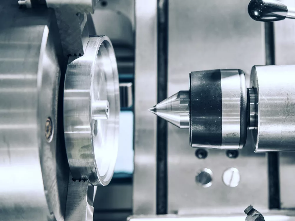
Creating a workholding system is an exercise in engineering design, even if the system is assembled from catalog components. The first step in design is to identify all of the functions that any successful design must accomplish, along with a list of requirements and constraints that define the performance objectives for achieving each function, and any inherent limitations on the hardware used to achieve them.
It’s always very tempting to just jump right in and start grabbing components and assembling them, but experience shows that better results are achieved if we take a few moments to step back from the hardware and first consider the design problem more abstractly. Doing this helps to make sure we fully understand what we want to achieve. In this article we will apply this methodology to the design of workholding systems.
FUNCTIONS PERFORMED BY THE WORKHOLDING SYSTEM
Hold the workpiece securely during machining to avoid unwanted motion on all axes. Rigid bodies have six degrees-of-freedom of motion in space, i.e. translations along the three coordinate directions, X, Y, and Z, and rotations about those same directions, Rot-X, Rot-Y, and Rot-Z. Motion can occur in the positive and negative directions of each of these degrees. 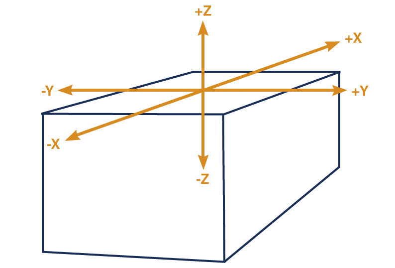
The workholding system must hold the workpiece in such a way that all of the surfaces to be machined are accessible to the cutting tools and within the range of the machine tool.
A method must be proved that allows new workpieces to be secured into the workholding system, and finished workpieces to be removed.
The workholding system must ensure that the axes of the workpiece coordinate system are parallel to the machine tool’s motion axes. The part must also be located within its workspace.
REQUIREMENTS OF WORKHOLDING SYSTEMS
The workholding hardware selected to perform the functions listed above must satisfy the following requirements:
Virtually all workholding systems rely on friction to restrain at least some of the workpiece’s degreesof-freedom of motion. Clamping forces must be high enough to generate frictional forces larger than the anticipated cutting forces.
Avoid excessive deflections of the workpiece due to the clamping forces. Workpieces are not perfect in geometry, which can cause problems during clamping. For example, consider a workpiece that is cut from raw bar stock, and contains a slight bend. If it is clamped in a vise in a manner that “straightens” the bend, that bend will reoccur after machining, likely leading to a finished part that doesn’t meet dimensional tolerances.
In some cases, workpieces have sections or features that are thin and flexible. For these types of parts, great care must be taken to design a workholding system that can clamp the part securely enough to resist the cutting forces without distorting it.
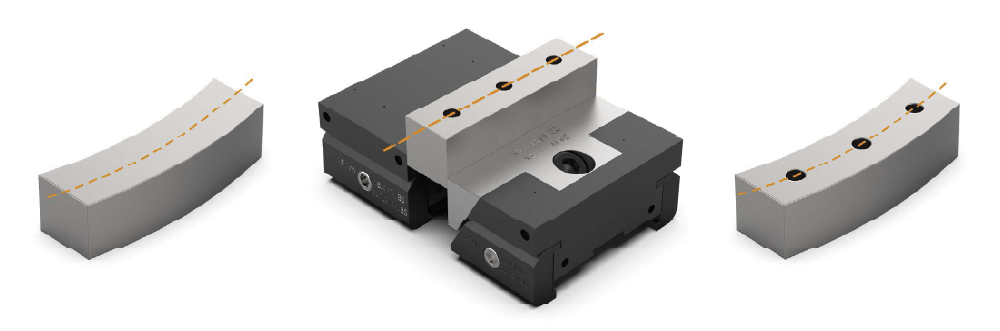
For workholding systems designed to hold multiple workpieces, the time required to clamp and unclamp them can be a significant contributor to cycle time. The economic benefits of more complex systems that clamp all parts with a single input motion, or automatically clamp and unclamp hydraulically or pneumatically, must be weighed against the added cost.
Orient and locate the part relative to the machine axes with precision. Nearly all raw workpieces lack precision surfaces to locate them, especially castings and forgings. For these parts, the requirements for orientation and location accuracy only need to be good enough to be comfortably accommodated by the machining allowance on the workpiece. However, it is often necessary to refixture a part to finish the machining of previously inaccessible surfaces. In these cases, the requirements for orienting and locating the part are much more stringent, and different strategies may be needed.
Avoid excessive deflections or vibrations under the cutting forces. All machine tool components, including workholding systems, deflect when forces are applied to them. The amount depends on how stiff they are. It can be useful to think of the machine tool and workholding system as a network of interconnected springs. These are generally very stiff springs, but the allowable deflections are also very small. Collectively, the spring system must be stiff enough so that the deflections resulting from the cutting forces are small compared to the overall tolerance requirements. The stiffness of the elements, combined with their masses and damping, will also determine the system’s vibrational response to the time varying cutting forces that occur in virtually all milling operations. Now the situation becomes more complex since these dynamic systems have natural frequencies or resonances, and when the rotational speed of the cutter causes the tooth passing frequency to be near one of these resonances, the amplitude of vibrational deflections can increase dramatically.
Very few shops have the luxury of production volumes and runs high enough that a machine tool and workholding system can be dedicated to a single part for their entire life. This means that workholding system components should be designed to provide flexibility and modularity so that they can quickly and easily adapt to new and different jobs.
CONSTRAINTS ON WORKHOLDING SYSTEMS
Workholding systems also face a variety of constraints that are typically machine dependent, including:
The workholding system must be able to physically fit within the machine’s work volume and be able to be loaded through the access doors.
All machine tools have maximum allowable weight limits the machine can safely accommodate. The fully loaded workholding system must not exceed this limit.
The workholding system will need to be tightly attached to the worktable of the machine tool. Therefore, its mating surface must be compatible with the attachment methods the worktable is designed to use.
Summary: Design of Workholding Systems
Part 4: Cutting forces in milling
One of the basic rules of engineering design is that it is “done with numbers”, rather than with vague assertions about the properties of the system being designed. It is of little use to say that we want our workholding systems to be “really stiff and strong” without specifying what level of stiffness or strength is sufficient.
Consider how you would react if a customer came to your shop asking for quotes on some parts, and said that they wanted the dimensions to be “very precise” and the surface finish to be “super smooth”. You would probably think the customer was naive, at best, and at risk of being taken advantage of by an unscrupulous supplier. When you go shopping for workholding systems it’s critical to know what level of performance you require so you won’t be that same type of naive customer.
In that spirit, this article will show us how to estimate the magnitude of cutting forces during a machining operation. Using that information we will be able to specify what performance we require from the components selected for our workholding system.
Two of the most important requirements of workholding systems are:
- Hold the workpiece against the cutting forces
- Minimize deflections due to those forces
The first requirement simply says that however the workpiece is held in the fixture, it will not loosen or be pulled out of the fixture by the cutting forces. The second requirement recognizes that tolerances and surface finish must be held, and to do so the workholding system cannot deflect or vibrate excessively in response to the cutting forces.
Of course, if we are trying to design or select a workholding system intelligently, we will need to know just how large those cutting forces are expected to be so that we can evaluate how the workholding system responds.
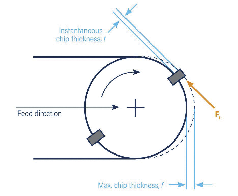
In milling, the edge of a rotating tool is forced through a stationary workpiece to form a chip. Most milling cutters have multiple cutting edges, and as the tool rotates each edge engages the workpiece, removes a chip, and exits. The figure below shows a top view of a slotting operation using a 2-fluted cutter. The cutter is rotating clockwise, and is being fed into the workpiece towards the right. The crescent shaped area bounded by the dashed line is the chip that will be removed by this edge. The next edge will remove a similarly shaped region, etc. The thickness of the chip as it is removed is zero when the edge first engages the work, grows to its maximum value after 90 degrees of cutter rotation, and then drops back to zero when it exits after 180 degrees of rotation.
At any instant during the rotation, there is a cutting force component known as the tangential cutting force, Ft, acting on the edge of the cutter that is tangent to the body of the cutter, i.e. perpendicular to a radial line from the cutter center to the edge. The magnitude of the tangential force is proportional to the axial depth of cut, b, which is nominally constant during a single cutter rotation, the instantaneous chip thickness, t, and is dependent on the type of material being cut.
The maximum value of the chip thickness, f, is the feedper-tooth, or chip load, selected by the programmer when choosing the well-known feed and speed parameters for the operation. Therefore, the cutting force will reach its maximum value when the edge is at 90 degrees, and the chip thickness is maximum.
There are also components of the cutting force directed from the edge towards the center of the tool, and along the axis of the tool. However, in practice these radial and axial cutting force components are normally a small fraction of the tangential force and contribute insignificantly to the total cutting force; so we will concentrate only on the tangential cutting force and simply refer to it going forward as the cutting force. As this figure shows, the cutting force is not constant in either magnitude or direction. This is a characteristic of virtually all milling operations, and is different from lathe operations where the single cutting edge is normally constantly engaged with the workpiece as it rotates, and the resulting cutting force is nominally constant.
Another thing to consider is, if the tool has more than two cutting edges, multiple edges may be engaged with the workpiece at the same time, each contributing their own cutting force; and the workholding system must be designed to counteract their combined total. If the cut uses a partial radial engagement, i.e. less than a full slot, the situation changes again with regard to when edges are in or out of the workpiece. If the radial engagement is less than half the cutter diameter, the maximum chip thickness never reaches the “feed-per-tooth” value, f.
At this point it might seem hopelessly complicated to try to calculate the cutting forces. Since they vary continuously during a cut, the workpieces held by the workholding system may vary substantially in size, shape, and material, and each different part being machined may use many different cutters, each with their own feed and speed, axial depth of cut, and radial engagement. Fortunately, in engineering design, we don’t generally try to analyze every single loading situation a structure might encounter in use. Instead, we want to create our design so that it is capable of withstanding the highest loads that are expected to ever occur.
For example, a bridge designer doesn’t bother to calculate the stresses and deflections of every member and weld in the bridge for the case of a small child on a bicycle crossing the bridge. Instead they base their analysis on their estimate of the largest loads that might be encountered, perhaps something like a closely spaced military convoy of tanks crossing the bridge. We will do the same for workholding systems.
Machining is a subtractive process in which every workpiece starts out with an initial volume, and ends with a smaller, final volume. Generally speaking, the larger the volume of material to be removed, the longer the time it takes to machine it away. Therefore, one key to minimizing cycle time is to maximize the material removal rate, or MRR; and high MRRs typically mean higher cutting forces and require higher spindle powers.
Most cuts do not consume the full spindle power, although it is good practice to maximize MRR as much as possible, considering constraints on tool breakage and wear, and surface finish. Nonetheless, it makes sense to see how high the cutting forces are when the spindle is operating at its full capacity and MRR is maximized, and use those values when we analyze the workholding system components.
For most machining operations it is easy to calculate the maximum value the total cutting force can ever reach using the rated power of the spindle motor. The simple formula below uses only three inputs, the spindle power, P, in horsepower, the spindle speed, n, in rpm, and the tool radius, rtool , in inches; and gives the cutting force, Ft , in pounds. This relationship holds regardless of the material being cut, the type of cutter used, the tool path, or the selected feeds and speeds.
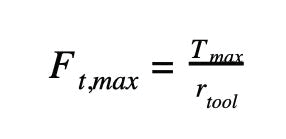
For instance, suppose your milling center has a spindle that is rated at 30 HP and you are cutting with a 1 inch diameter tool at a spindle speed of 2500 rpm; the tangential cutting force will be Ft,max=1512 lbs when axial depth and chip load cause the spindle to operate at max power, and somewhat less than that for any operation that does not consume the full power of the spindle, and therefore has a lower MRR. The workholding system must be robust enough so that forces of this magnitude don’t loosen the part from the clamping system, and any deflections or vibrations resulting from forces this large do not cause problems with tolerances or surface finish of the finished part.
The formula above shows us that for a given spindle power and speed, as the tool diameter increases, the maximum cutting force the spindle can generate decreases, so a 2-inch diameter cutter can only create cutting forces that are half those for a 1-inch cutter, or 506 lbs. Increasing the spindle speed can also reduce the maximum cutting force, especially for smaller diameter tools; but at some point as we try to maximize MRR for smaller diameter tools, the cutting forces can become so large that the tool either breaks or wears out prematurely.
In this instance, the limit on MRR is not caused by insufficient spindle power; and the cutting force will generally be lower than for the max power case. Nevertheless, we should design our workholding system and select its components to be capable of handling the cutting forces caused by the max power case, should that arise.
Variable speed electric motors, like machine tool spindles, generally are not capable of delivering their full rated power at all speeds. Similarly, they usually cannot deliver their full rated torque at all speeds.
Not all machine tool OEMs provide information about spindle torque to their customers, and in that case we will need to rely on the max power to estimate the maximum cutting force that might be exerted on the part, and thus on the workholding system.
If you know the maximum torque rating of your spindle motor, Tmax , it is easy to calculate the max cutting force using the formula below, where Tmax is in inch-lbs, and rtool is in inches.
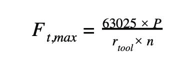
If the maximum cutting force calculated from the spindle torque rating is higher than that from the maximum power rating, then we will use that value. In practice, the two estimates are usually similar, and since we will be using generous safety factors either is suitable for our purposes.
From the diagram above we also see that a single cutting edge cannot engage the workpiece for more than 180 degrees of tool rotation in a slotting cut. Most milling operations use less than a slotting cut, so the tooth’s angle of engagement in the work is even less.
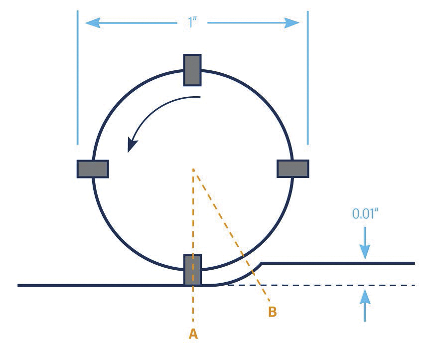
If the radial depth-of-cut is very low, the tooth may only engage for a small part of a revolution of the tool. For example, consider a finishing operation using a one-inch diameter end mill with four teeth, as shown in the figure below. If the finishing pass removes 0.010” of material, the cutting edge enters the workpiece at Position A and leaves it at Position B. A little trigonometry shows us that the tooth is only engaged with the workpiece for 11.5 degrees of rotation. The next tooth doesn’t engage the workpiece for another 78.5 degrees of rotation, meaning that in this cut the tool makes no contact whatsoever with the workpiece for approximately 88% of the time; and during that time the cutting force is zero.
The cutting force here is actually a series of short pulses or impacts that occur at the tooth passing frequency; and anyone who has operated a milling machine will now understand that the distinct sound of the process is actually caused by the varying force as each tooth in succession engages and leaves the work. This periodically varying nature of the cutting force is characteristic of virtually all milling operations, and naturally it can lead to excessive vibrations if the workholding system is not properly designed.
In extreme cases, if the workholding system is too flexible the vibrations can turn into full-blown chatter, resulting in very poor surface finish and potentially damage to the cutting tool or machine. The dynamic vibrational response of the workholding system to the periodic variations in the cutting force should ideally never be the limiting factor in how aggressive the machining operation can be in pursuit of maximizing MRR to lower cycle time.
Summary: Cutting Forces in Milling
Part 5: The Role Of Stiffness In Workholding
In article 4, we showed how to estimate the maximum cutting force a workholding system could experience on a given machine tool. In this article we will show how to calculate how the elements of a workholding system respond to those forces; in particular, how they deflect.
In a previous article we urged you to start thinking of your machine tools as a collection of springs connected together in a chain with the tool at one end and the workpiece at the other. When we add a workholding system, we are adding another spring to the chain; and it needs to be stiff enough so that the behavior of the machine when cutting doesn’t change significantly.
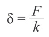
A spring is a mechanical element that deflects when a load is applied to it, and recovers its original shape when the load is removed. The amount a spring deflects under a given load is called its stiffness, and is designated as k. The amount, , a spring deflects under a load is given by the formula below. For example, if a spring has a stiffness of 20,000 lbs/in, that means that a force of 20,000 lbs will cause it to deflect one inch. A force of 10,000 lbs will cause it to deflect one-half inch, etc.
It can be difficult to think of massive machine columns and beds as springs because their stiffness is so high that their deflections can’t be perceived by ordinary human senses. However, it is still useful to do so. There are no absolutely rigid bodies in the world. Even the most massive structural component deflects under the smallest loads. The appropriate question isn’t whether the elements in a machine tool deflect under the action of the cutting forces, but whether the amount of deflection is enough to negatively impact the machining process and the part’s quality. Stiffness is one of the most important qualities of a machine tool, and plays a huge role in how aggressively the machine can cut material, and the dimensional and surface quality of the resulting part. Machine tool designers expend tremendous effort to make sure the composite stiffness of all the elements in the chain running from the tool tip to the workpiece is sufficient to allow the machining process to utilize the full power of the spindle.
It wouldn’t make sense to put a Corvette V-8 in a go-kart, or a lawnmower engine in a Ferrari. The engines used in both are compatible with the rest of the drivetrain and vehicle frame, to use full engine power without going overboard. In a similar way, machine tool structures are designed to be compatible with the spindle motor used in the machine. The structure must be stiff enough so that the full power of the spindle can be used, and when we add a workholding system, it needs to be stiff enough that we don’t degrade the machine’s performance.
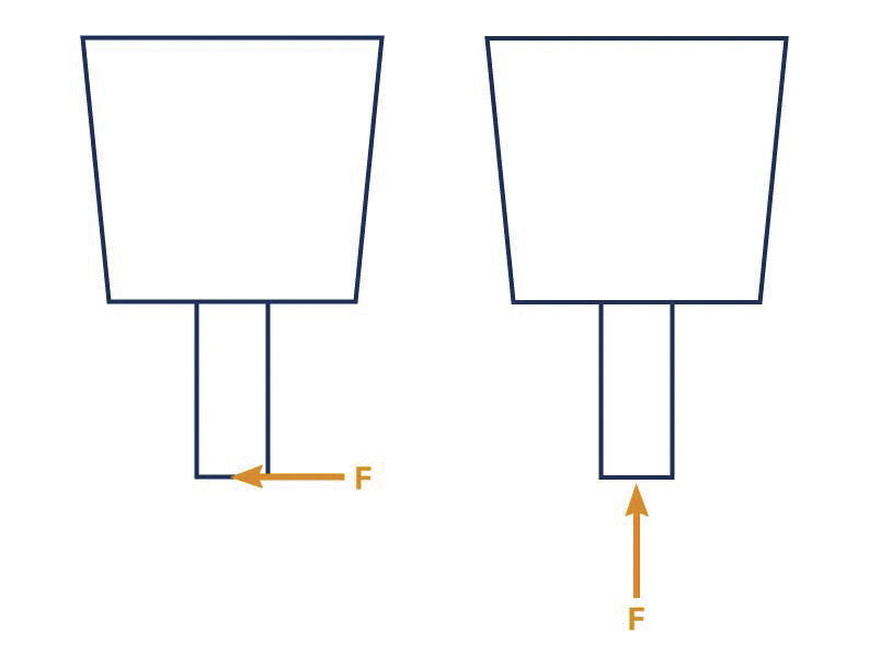
Of all the ways workholding system components can deform, bending is almost always the most flexible. For instance, let’s think about a steelbodied milling cutter that is 1 inch in diameter and 4 inches long. If we assume that it is connected to a rigid tool holder and spindle system, then the tool acts like a cantilever beam when the cutting force is perpendicular to the tool axis. This causes the tool to deflect to the right, and its bending stiffness is 69,029 lb/in. On the other hand, if the cutting force acts along the axis of the tool and causes the tool to shorten, the axial stiffness is 5,890,500 lb/in. That’s 85 times higher than the bending stiffness.
The same force will cause deflections that are 85 times higher when applied perpendicular to the tool axis compared to along it. This predominance of bending is always the case unless the length of the structural member starts to approach its thickness. For this post, we will only consider bending when analyzing workholding elements.
In most cases, the tombstone is the element of the workholding system that is most likely to undergo bending. In the figure below we see a typical rectangular tombstone with height, h, width, w, and thickness, t. It is mounted on a 19 machine worktable which we will consider to be rigid, and so the tombstone acts like a cantilever beam when a cutting force, F, is applied. The formula for stiffness of a rectangular cantilever beam, with the load applied in the thickness, t, direction is:
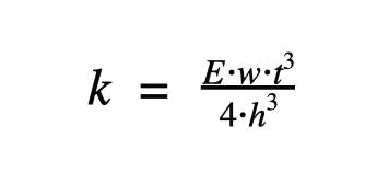
In this formula, E is a material property known as the modulus of elasticity. The value of E for common tombstone materials is listed in the table below. For steel and aluminum, the value of E is the same regardless of alloy or heat-treat. For cast iron, there is dependence on the exact type of iron, but for typical tombstones use the value below.
| Material | Modules of Elasticity |
| Steel | 30,000,000 |
| Cast Iron | 21,000,000 |
| Aluminum | 10,000,000 |
Therefore, if the tombstone pictured above is made of steel and has dimensions of h=24 in, w=12 in, t=6 in, its stiffness will be k=1,406,250 lbin. If the cutting force is F=1000 lbs, the top of the tombstone will deflect by 0.0007 inches. If the tombstone was made of aluminum instead of steel, the stiffness would be reduced by twothirds and would deflect 0.0021 inches, which could lead to missed tolerances.
If we look more closely at the stiffness formula above, we see some interesting things. First, the values of height and thickness have very strong effects. If the thickness is doubled, the stiffness increases by a factor of 8. In fact, if we increase the thickness of the tombstone by 1 inch to 7 inches, the stiffness increases by almost 60%. Conversely, if the height is doubled, the stiffness decreases by a factor of 8. The width of the tombstone does not have such a large effect on stiffness since doubling it only doubles the stiffness.
Second, we can see that where the workpiece is placed on the tombstone can have a dramatic effect on the stiffness. If the workpiece is placed half-way up the tombstone instead of at the top, the effective height of the tombstone is now just 12 inches, since the portion above the part isn’t being subjected to any load. Now the stiffness at the point where the part sits is 8 times higher 20 than if it were placed at the top, and the 1,000 pound cutting force will only cause a deflection of 0.00009 inches in the steel tombstone, and 0.00027 inches in the aluminum tombstone.
Tombstones are often made hollow to decrease their weight. Doing so certainly decreases their stiffness, but not by as much as you might expect. Essentially, the stiffness of a hollow tombstone is equal to the stiffness of the solid tombstone minus the stiffness of a solid tombstone the size of the inner cavity. So, if the steel tombstone in our example was welded from 1 inch thick steel plate it has an interior rectangular cavity measuring 10 inches wide by 4 inches thick by 23 inches high. The stiffness of the hollow tombstone is khollow=1,011,740 lbin. Thus the stiffness decreased by only 28% while the weight decreased by nearly 47%.
Of course, tombstones are not all made in convenient rectangular shapes, and for those outliers the formula above does not work. While it is possible for a trained engineer to figure out the stiffness for this new shape, you can easily get a lower-bound estimate by figuring out what the largest rectangular shape is that would fit inside the tombstone, and calculating that stiffness. The real tombstone will certainly be stiffer than this value, perhaps substantially. However, if the value you calculate is satisfactory, the real tombstone should function well.
As previously mentioned, the machine tool structure that connects the tool point to the workpiece can be thought of as essentially a large spring that has some stiffness. What happens when we add another spring, i.e. the tombstone, onto the end of that chain? It turns out that the addition of even what seems to be a very stiff tombstone can have significant negative effects.
For example, suppose that a structure’s composite stiffness from the tool tip to the workpiece is 500,000 lb/in. It seems appropriate to add a tombstone with a stiffness of say 1,000,000 lb/in. Unfortunately when we do, the composite stiffness now becomes 333,333 lb/ in, or a 33% drop; meaning the machine is no longer able to work at full power. In order to limit the drop in composite stiffness to less than 10%, the tombstone needs to be at least ten times as stiff as the composite stiffness of the rest of the machine, and preferably more.
Fortunately, for most machine tools the most flexible element is the combination of the cutting tool, tool holder system, and the spindle shaft. Machine tool designers usually try to make the composite stiffness of the structure at least 10 times the stiffness of the tool/ holder/spindle combination. If we use tombstones that are also 21 10 to 20 times that stiffness, then we should not compromise the cutting performance of the machine significantly.
The deflection you calculate for your tombstone using the formula above is what would happen if the force were applied slowly and then held constant. Unfortunately, as we saw in part 4, cutting forces are not static, but vary periodically at the tooth-passing frequency, causing vibration. For virtually all tombstones, the vibrational deflections, or amplitudes, will be larger than the static load case, sometimes substantially larger. In the next part we will look at how mechanical systems vibrate and how the design and material of the tombstone can affect how large those vibrations are.
Summary: The Role of Stiffness in Workholding
Part 6: Vibrations
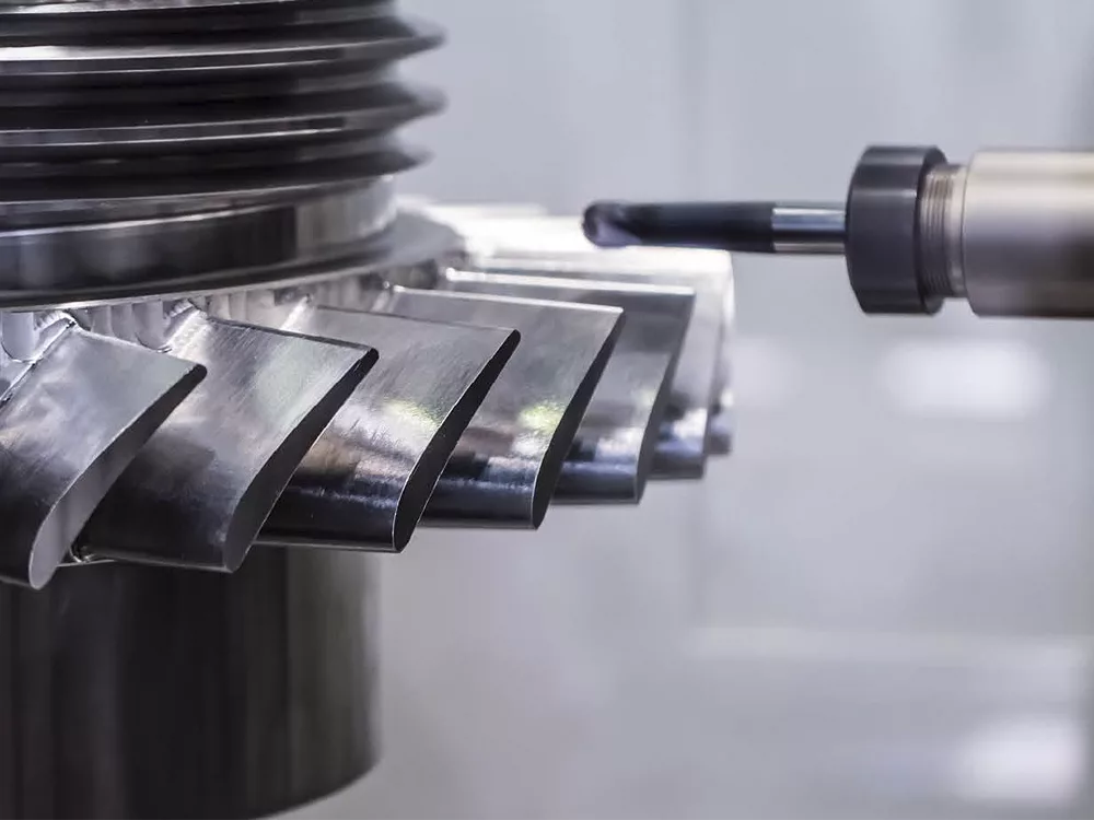
In part 5, we showed how to estimate the deflection on a tombstone, based on the expected maximum cutting force. However, the deflections we calculated assumed a constant load, and are only the static deflections. We have already seen that the cutting force is never constant, but varies at the tooth-passing frequency. For example, if we have a 4-fluted cutter rotating at 3000 rpm, or 50 revolutions per second, a new tooth will engage the workpiece 200 times per second, or 200 Hertz (Hz). This periodic force causes mechanical systems to vibrate. Let’s consider our tombstone’s response.
When a mechanical system is acted on by a periodic force, the system will vibrate at the same frequency as the applied force. This is known as a forced vibration, and is different from a free vibration where a very brief input force is applied and the system vibrates on its own, like ringing a bell. In free vibrations, the system vibrates at its natural, or resonant, frequency; and the vibrations eventually die out because all real structures have damping. Damping causes the amplitude of the vibrations to decrease over time. The higher the damping, the faster the vibrations die out.
So, in the example above, the tombstone will vibrate at the forcing, or tooth-passing, frequency of 200 Hz. The amplitude of vibration, or the maximum deflection during a single cycle, is dependent on the ratio of the tooth-passing frequency to the natural frequency. The figure below shows how the system will respond.
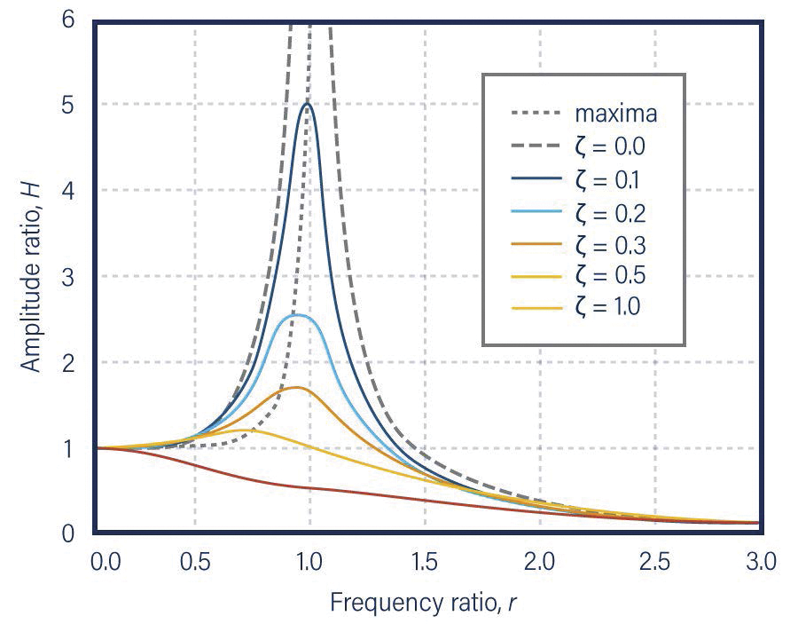
In this graph, the vertical axis is H, the ratio of the amplitude of the vibration to the static deflection caused by the maximum cutting force (if it were constant). The horizontal axis is r, the ratio of the tooth-passing frequency to the system’s natural frequency. So, if the force is constant, meaning its frequency is zero, then the frequency ratio is zero, and the amplitude ratio is 1, meaning that the system undergoes its static deflection.
On the other hand, if the forcing frequency is equal to the natural frequency of the system, or r=1, the amplitude of vibration can be very much larger than the static deflection. The colored lines show how the amplitude varies for different values of the damping ratio, , which is normally designated by the lower-case Greek letter, zeta. For virtually all workholding systems, and machine tool components, the damping ratio is quite small. Typically for metal tombstones it will be less than =0.25, meaning that when the toothpassing frequency is the same as the resonant frequency, the amplitude of vibrations will be more than twice the static deflection that would be caused by the cutting force if it were constant. In general, for lowly damped systems, the peak amplitude ratio occurs near to the resonant frequency and is approximately equal to Hmax=12r.
In part 5, we calculated the static stiffness for a solid steel tombstone with dimensions of 24x12x6 inches, and found that for a static force of 1000 lbs, the tombstone would deflect by 0.0007 inches. If that tombstone has a damping ratio of =0.2, and the tooth-passing frequency equals the natural frequency, then the vibration amplitude will be approximately 0.0018 inches. Since the amplitude is measured from the undeflected position to the max deflection, the total motion will be twice as much. The tombstone surface will move from +0.0018 inches to -0.0018 inches, for a total excursion of 0.0036 inches. This starts to become concerning as it is likely a significant fraction of the tolerances you would like to hold, and is many, many times higher than the peak-tovalley difference in common surface finish specs. Fortunately, as we will see shortly, just because the workpiece attached to the tombstone is moving this much does not mean that the surface roughness will also be that bad.
We can see from the above that the maximum amplitude of vibrations in response to a given cutting force is primarily determined by two characteristics of the tombstone. These are the static stiffness and the damping ratio. The product of these two, k , is called the dynamic stiffness; and this is what we need to look at when comparing tombstones of different geometry and materials. In a future section we will compare measured values of dynamic stiffness for common tombstone materials.
When we calculate the potential amplitude of vibrations for realistic cutting forces and tombstone dimensions and materials, we will often find values that are much larger than the surface finish specification. This seems like it would almost certainly lead to unacceptable parts. Fortunately, one characteristic of forced vibrations is on our side in this instance. To understand that, we need to look more closely at how the surface of a milled workpiece is actually created. In the figure below, we see an end view of a milling cutter as it progresses through a part from left to right. The feed-per-tooth is greatly exaggerated here so that we can see how the individual teeth create the newly milled surface. For the moment we will assume that the tool feeds smoothly to the right and the tombstone to which the part is attached is perfectly rigid and experiences no vibrations.
The blue, orange, and teal curved lines show the surface left behind as each tooth successively engages the workpiece and removes a chip. Most of the curved surface left behind by one tooth is removed by the next. What remains are small scallops with shallow peaks separated by the feed-per-tooth distance, commonly referred to as “feed marks.” For normal machining parameters, the height of the peaks is quite small. For instance, if the cutter diameter is 1 inch, and the feed-pertooth is 0.01 inches, the scallop height will be about 25 millionths of an inch and the peaks will be separated by 0.01 inches.
Now, let’s assume the part surface, which is attached to the tombstone, is vibrating vertically up and down by several thousandths of an inch as the tool moves to the right. This seems like it would create a horribly rough surface, but we are saved by a vital characteristic of forced vibrations, specifically that the deflection has a constant phase relationship to the force. This means that each time a tooth rotates to a point where it is just beginning to engage the surface, the tombstone and part will always be in the same vertical location of the vibration. Exactly where it is in the vibration depends on the frequency ratio, r, but fortunately it will be at the same vertical position for every tooth.
Note that as the spindle speed changes, the vibrational position where the new surface is created will change slightly. However, this is normally a small effect unless one is machining with a tooth-passing frequency which is near the resonant frequency. In that instance, small changes in the spindle speed can lead to significant changes in the location of the new machined surface. It is generally best to avoid spindle speeds that are near the resonant frequency of the tombstone.
This fortunate situation will be true so long as the cut remains stable. If the cut is too aggressive and begins to chatter, the vibrations will no longer be at the toothpassing frequency. This means that each tooth will create its part of the machined surface at a different vertical position, leading to the horrible surface finish characteristic of surfaces machined with chatter.
For most well-designed machining centers, the tool, holder, and spindle-shaft system is the most flexible element by a wide margin. The reason for this is that the bearings that support the spindle shaft cannot be too large in diameter and still able to spin at the speeds normally expected in modern machine tool spindles. Therefore, the diameter of the spindle shaft is limited by the bearings that support it, and the shaft diameter is the dominant factor in deciding the system’s bending stiffness.
Ideally, you would directly measure the dynamic stiffness of the spindle/holder on your machine. The best way to do this is with a “tap test” that utilizes an instrumented hammer to tap the spindle nose and measure the force versus time of the impact. An accelerometer attached to the opposite side of the spindle nose measures the resulting vibrations, and software processes the signals to provide a “frequency response function”, which extracts the static stiffness and damping ratio values. Unfortunately, most shops don’t have this equipment. However, there are services you can hire to come to your shop and measure your machine spindles. They can also measure the stiffness and damping of tombstones or other workholding devices. The tests are quick to set up and run, so in most instances they are able to measure all of the machines of interest in a single visit.
If it isn’t feasible to measure the dynamic properties of the spindle on your machine, you will have to fall back on experience. Generally speaking, the larger and more powerful the spindle motor, the stiffer it will be. However, for typical machining centers with spindles rated up to around 40 HP, the dynamic stiffness of the spindle/holder system will rarely exceed 50,000 lb/in, and in many cases it will be much less, especially if long, slender end mills are used. We generally want the dynamic stiffness of our tombstone to be at least 10 to 20 times larger than the dynamic stiffness of the spindle/ holder system. Therefore, if no spindle dynamic measurement data is available, it would be best to target tombstones with dynamic stiffness above 500,000 lb/in. Of the common tombstone materials, epoxy mineral and cast iron generally offer the highest dynamic stiffness properties, with aluminum having the lowest. Steel generally falls between aluminum and cast iron.
Summary: Vibrations
Part 7: Workholding System Components
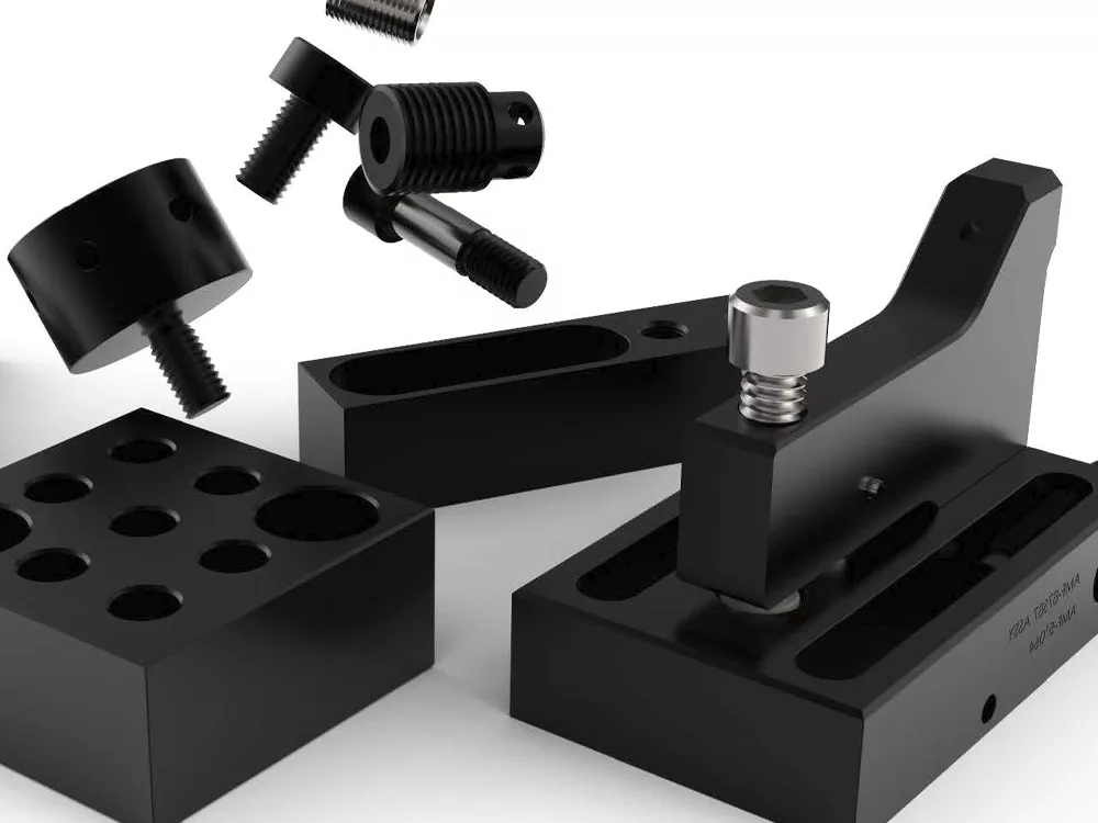
Complete workholding systems are composed of a number of components, each of which contributes to fulfilling one or more functions. In part 3 of this series, we listed the primary functions that all workholding systems must perform:
- Hold the workpiece(s) securely against the machining forces.
- Provide access to the surfaces to be machined.
- Clamp and release the workpiece(s).
- Align the workpiece(s) to the machine’s coordinate axes.
- Locate the workpiece(s) origin(s) relative to the machine’s origin.
In upcoming sections, we will examine types of components that can to accomplish these functions, recognizing that many workholding system components contribute to more than one of the functions listed above. We’ll use the following criteria to evaluate and compare them:
Improving productivity and reducing cycle time is one of the most important aspects of workholding. This can come from:
- More efficient use of the machine’s work volume to allow multiple parts to be machined in the same setup
- The ability to more rapidly load and unload parts
These advantages must be weighed against the time and effort required to set up the workholding system.
Except in very high production environments, most shop owners and managers will want to invest in workholding systems that are capable of handling a wide variety of workpiece shapes and sizes.
Ideally, the workholding system will accommodate workpieces directly as supplied without preliminary operations to machine locating or clamping surfaces. However, these operations may be required where there is wide variation in the dimensions of the raw workpiece, such as with castings or forgings. They may also be needed to better resist high cutting forces or to provide machining access to blocked surfaces, eliminating the requirement for refixturing.
The majority of clamping systems use friction to restrain the workpiece in at some directions. The clamping force must be sufficient to create frictional forces large enough to resist the machining forces; yet low enough to avoid distorting or damaging the workpiece.
All real mechanical systems deflect when forces are applied. In previous articles in this series we looked at the machining forces which the workholding system must withstand. The static and dynamic stiffness of the system is of paramount importance in reducing deflections and minimizing vibrations.
Many workpieces have machined features on multiple sides. It is highly desirable to avoid having to refixture the part to access these features. Therefore, the workholding system should maximize cutting tool access to multiple surfaces of the workpiece.
Workholding systems are commonly used to align and locate the workpiece(s) within the machine’s workspace, reducing the need to “indicate” the parts into alignment, or to “touch off” surfaces on the part. The accuracy and repeatability with which the workpieces are aligned and located is critical to achieving the desired productivity gains.
Not all shops have the luxury of production volumes high enough that machines and workholding systems can be dedicated to making a single part for their entire useful life. In those cases, the components of the workholding system should be able to be reconfigured to allow for different jobs. Modularity is often a key characteristic to achieve this.
Workholding systems ideally improve productivity. However, to also improve profitability, the system cost must be such that it provides an adequate return on investment (ROI).
Part 8: Workholding Clamping Systems
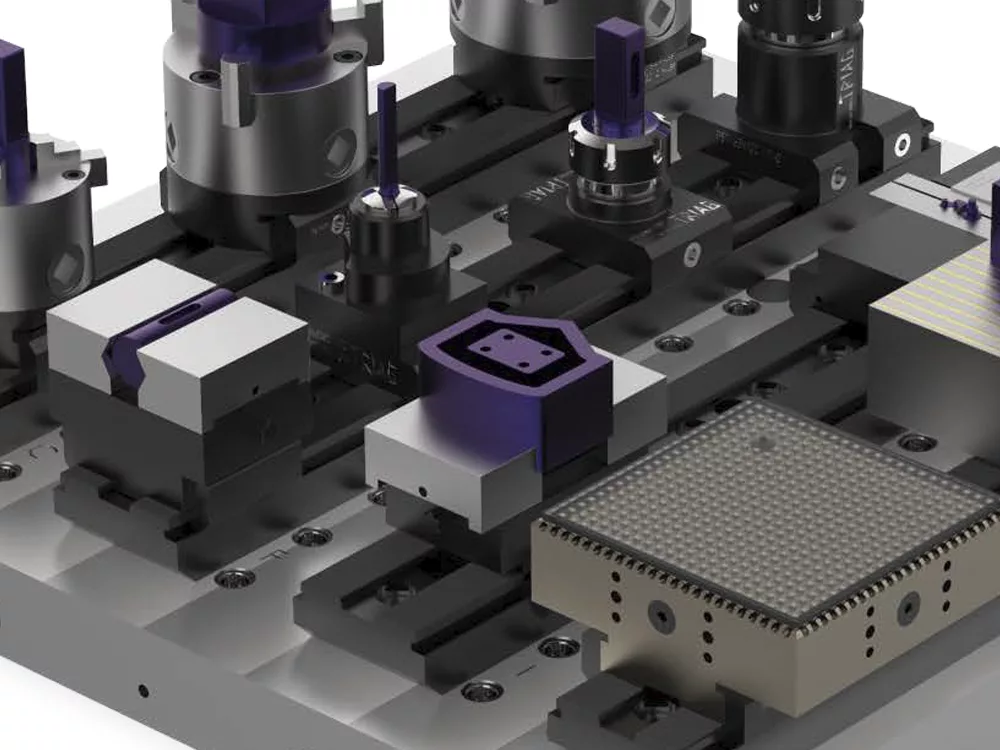
The one component that is common to all workholding systems is a method for clamping the part(s). As we discussed earlier, machining involves forces that can be significantly high, and a clamping system is needed to restrain the workpiece from moving. A wide variety of clamping systems exist, and it can be difficult to choose which one is best for your needs. In this section, we will look at the various types of clamping systems and evaluate their strengths and weaknesses. All clamping systems must be able to accomplish the following tasks:
- Enable workpieces to be loaded and unloaded in a fast and efficient manner
- Accommodate workpieces of varying size
- Locate and align the workpiece relative to the machine’s axes, ideally without the need for indicating or touching off of surfaces
- Apply appropriate levels of clamping force to restrain the part being machined
In this article, we will examine the ways in which commercially available clamping systems accomplish the tasks above. The criteria below may be used to evaluate the various types of clamping systems.
- The time and effort required for setup
- The speed with which parts can be loaded and unloaded
- The range of part sizes that can be accommodated
- The amount of clamping force generated
- The amount of access provided to the part surfaces for machining
- The extent to which workpieces must be pre-machined or otherwise undergo special preparation in order to be compatible with the clamping system
- The flexibility the system provides to be reconfigured to accommodate different jobs
A majority of clamping systems use friction to restrain the workpiece in at least some directions. It is worthwhile to look more closely into some common situations to determine just how high the clamping forces need to be. The figure below illustrates a workpiece clamped along its lower edges while being machined along its top surface.
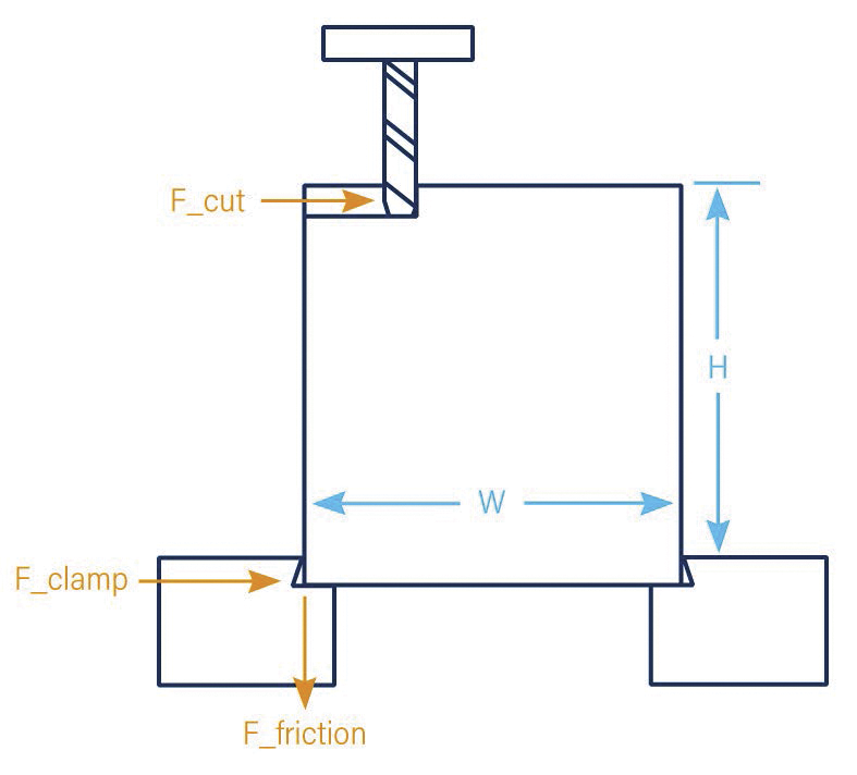
The cutting force will try to tip the part about the lower right-hand corner, and the friction force must be sufficient to prevent this. The clamping force should be at least five times the required friction force, and preferably higher.
Cutting forces are commonly hundreds of pounds, and for heavy cuts performed by a powerful spindle they can be thousands of pounds. If we assume the cutting force is 500 lbs, and the workpiece is 4 inches tall and 2 inches wide, the minimum clamping force required is 5000 lbs.
There are certainly cases where it is difficult to achieve enough clamping force to restrain the part by friction alone. If it is acceptable to mar the surface of the workpiece, systems exist that are designed to dig into the surface with hardened points or edges; thereby greatly increasing the effective “friction” force. Examples include the Pitbull Clamp by Mitee-Bite Products LLC, which is available in both blunt and knife-edge versions. According to the manufacturer, “...the knife edge clamps bite into the material for more aggressive machining, while the blunt edge is less likely to mark the workpiece.” Triag International also offers clamping surfaces that are designed to bite into the workpiece to achieve higher holding forces.
Another approach to minimizing reliance on friction is to use specially prepared workpiece features that mate with features on the clamp to cause mechanical interference to prevent motion. For example, 5th Axis offers a line of dovetail clamps that require a dovetail feature to be machined on the bottom of the workpiece. When mated with their clamping components, mechanical interference in the dovetail prevents the part from being pulled up out of the clamp. While this does require an additional machining step, it enables the use of lower clamping forces resulting in less part distortion. It also creates a very low-profile clamping zone which may result in less material waste on the workpiece, and enhanced access for 5-sided machining.
The speed with which parts can be loaded and unloaded is highly dependent on the method by which the clamping force is applied and released. By far the most common manual method is a screw-operated system, where the operator applies a wrench or other tool to the clamp to create and release the clamping force. Ideally, these manual systems should be operable using onehand only, so that the operator’s other hand can grasp the part and position it for clamping. Where possible, it can save time if multiple parts can be clamped or released with one actuation. For example, Mitee-Bite makes a line of Uniforce® clamps that work by forcing a wedge-shaped element in a u-shaped channel, thus elastically expanding the sides and creating a clamping force on two parts simultaneously.
If production volumes make it economically feasible, various forms of automated or semiautomated clamping actuation are available. The most common are hydraulic and pneumatic systems, where actuators powered by these energy sources replace the manually operated screw actuation. Hydraulic systems are generally more complex and expensive, but offer much higher clamping forces since they typically operate at several thousand psi; whereas pneumatic systems using shop air are typically limited to around 150 psi, and thus may require some sort of mechanical force amplification system to achieve the desired clamping force.
Clamping systems are also available that use magnetic attraction or vacuum to hold the part against a typically planar surface. Obviously magnetic systems are limited to use with ferromagnetic materials, but they can be designed to exert high clamping forces. These systems are often made so that rare-earth, permanent magnets hold the workpiece during machining so no power is required. To release the part, a brief pulse of electrical power is supplied to electromagnets that are arranged to counteract the magnetic attraction of the permanent magnets. Schunk International makes a wide variety of magnet chucks designed for milling applications. Vacuum clamps require large surface areas of the workpiece to be in close contact with the vacuum plate, since the vacuum is limited to atmospheric pressure, or about 14.7 psi. For example, a 4” X 4” workpiece will generate in excess of 200 lbs of suction force, which may not be sufficient for heavy machining. Much will depend on the friction between the workpiece and the surface of the vacuum chuck.
Except in very high production environments, most shop owners and managers will want to invest in clamping systems that are capable of handling the widest variety of workpiece shapes and sizes. The simplest way to accomplish this is with a traditional single-action vise as illustrated below, which uses one fixed jaw and one movable jaw actuated by a long screw. While this type of vise can accommodate a wide range of part sizes, it is wasteful of space in the machine and can take a long time to adjust from narrow to wide parts.
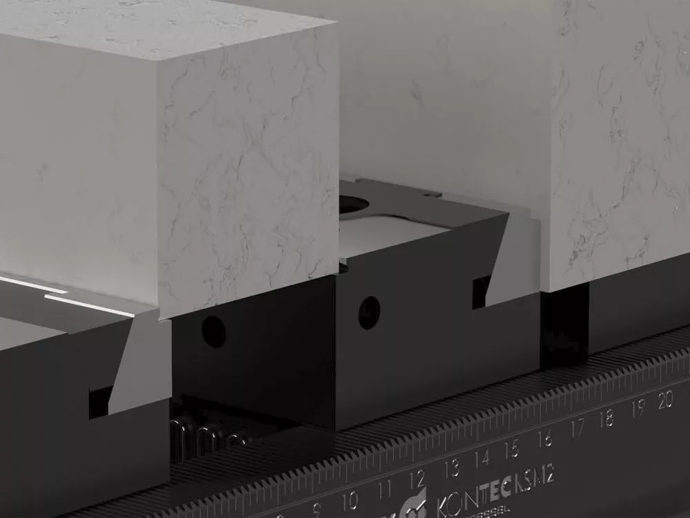
To address these shortcomings, many manufacturers offer modular systems where the fixed and movable jaws are easily repositioned along serrated tracks. The pitch of the serrations defines the lower limit of adjustability of positioning the jaws, with typical values in the range of 0.1 inches. An advantage of this is that the movable jaw only needs to travel a bit more than the pitch of the serrations, enabling a wider variety of methods to actuate the clamping force. A Schunk system is shown below, which uses a wedge principle to actuate the movable jaw. In this system, the reverse side of the movable jaw acts as a fixed jaw for the next clamp in the line.
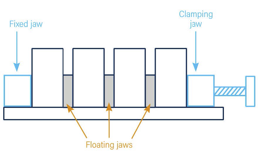
It is highly desirable that the clamping system align each workpiece with the machine’s axes, and locate it at a known point in the machine’s workspace. The most common way to achieve this is to have a fixed jaw against which each workpiece is clamped. While it is theoretically possible to use one fixed jaw and multiple floating jaws to clamp multiple workpieces with one clamping device, this is generally not a good idea. In the schematic figure below we see such a system that uses one clamping device to clamp four workpieces. When the movable jaw is tightened, the same clamping force is applied to each workpiece. While this seems like it would save a lot of time in loading and unloading, the problem is that unless the dimensions of the workpieces are tightly controlled, the total variation in size becomes the possible difference in position of the workpiece nearest the movable. This may make it difficult to hold tolerances in the workpieces furthest from the fixed jaw. Therefore, in general one should select clamping systems where each workpiece is clamped against a fixed surface to make sure the machine operator doesn’t have to touch off each part before machining can begin.
An alternative to fixed jaw clamping systems is useful when the raw workpieces in a production run vary considerably in size, as may occur with castings or forgings. For these, a self-centering vise may provide better part location. In a selfcentering vise, both jaws are movable and are designed to move symmetrically about a fixed center point between the jaws. The principle method by which self-centering vises maintain symmetrical motion is through the use of leadscrews with right and left hand threads, similar to a turnbuckle. The figure below shows a self-centering vise from Advanced Machine & Engineering. This vise also utilizes a dovetail gripper as described above, and is designed to accommodate mounting on precision grid plates with a 2-inch grid of locating holes.
There are four principal mechanisms by which manual clamping devices generate clamping force, screws, wedges, cams, and levers. If this sounds like the lesson on simple machines from your grade-school science class, it should! All of these well-known mechanisms are found in workholding clamping systems.
Screws: The most common example of a screw being used to generate a clamping force is the common bench vise. In this device, the screw is fixed in place axially, and the movable jaw of the vise is essentially the nut that is forced along the screw when it is rotated. A screw is essentially a long inclined plane, or wedge, that is wrapped around a cylinder to save space and make it easier to actuate. The amount of axial force that can be generated for a given input torque is dependent on the diameter of the screw, the thread pitch and number of leads, and the friction between the screw and the nut. If you select one of these for your clamping devices, it is very important to maintain good lubrication between the screw threads and nut to minimize friction. This will greatly increase the amount of clamping force you can create.
Wedges: For clamping devices where a short throw is acceptable, wedges can be used to create the clamping force. We showed an example of this in the Uniforce® clamp from Mitee-Bite. Of course, this clamp is actually actuated by a screw, and the wedge is used as a force multiplying device to create a clamping force that is much higher than the axial force in the screw.
Cams: A cam is similar to a wedge, except the inclined surface is wrapped around a cylinder, and the actuation is achieved by rotating the cam instead of pushing the wedge along its axis. An example of this type of clamp is the Series-9 clamp from Mitee-Bite. Here, the head of the actuating screw is placed slightly offcenter from the threaded body. When the screw is turned, the clamp edges are simultaneously forced into the material and provide downward force.
Levers: The use of levers is less common in clamping devices than the other methods described above. This is primarily because the mechanical advantage of the lever is fairly small unless the lever is quite long. Nevertheless, levers are used as force-multiplying devices in the Pitbull clamp from Mitee-Bite. In these devices, the clamp body pivots about one end when the screw is tightened. This forces the opposite end to move both outwardly and down, thus simultaneously creating both a horizontal clamping force and a downward force to better hold the part.
Summary: Workholding Clamping Systems
Part 9: Tombstones & Fixture Plates
Tombstones
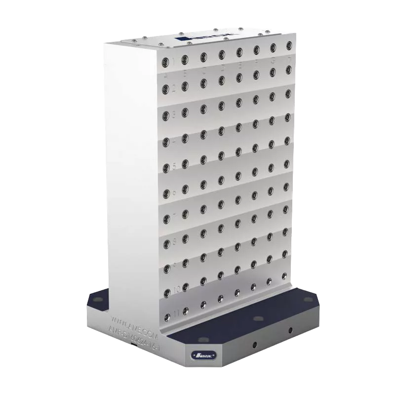
Many workholding systems are built around a tombstone, angle plate, or some other rigid structure as the central component, or foundation. One of the primary reasons for using a tombstone is to more efficiently utilize the machine workspace, especially for horizontal spindle machining centers. When a machine is being used to make parts that are substantially smaller than the work envelope of the machine, a properly selected tombstone can improve productivity and decrease cycle time by allowing for multiple workpieces to be fixtured simultaneously. This can cut down on the tool change part of cycle time, since the same operation can be performed on all of the workpieces before changing tools. Also, the load and unload time can be decreased by intelligent selection of the clamping components; and the machine can often then run unattended for longer periods of time, freeing up machine operators for other tasks.
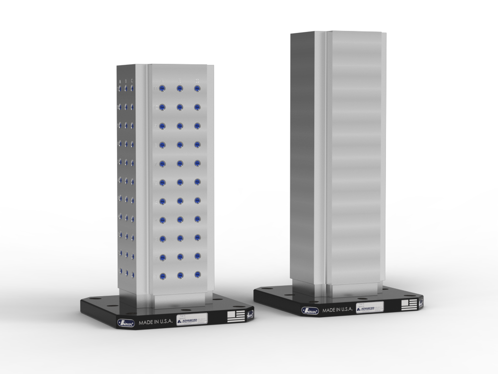
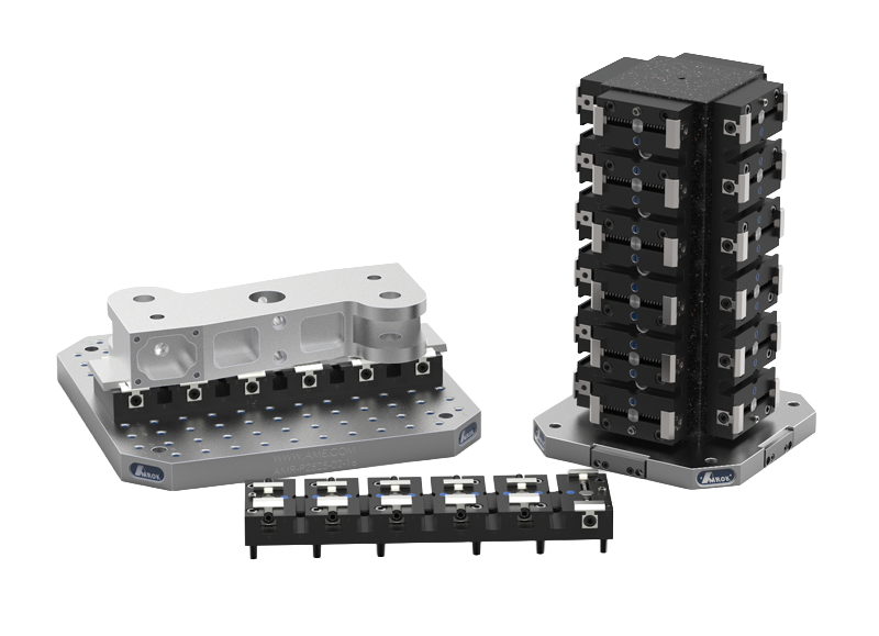
There are a large number of tombstone suppliers. AMROK, a part of Advanced Machine & Engineering (AME), is one of the largest and most well-known suppliers of tombstones and workholding foundations, CNC Tombstones & Subplates, Custom Fixtures, and Workholding Systems. They have a broad product line, and also provide custom-designed turnkey systems that are integrated with vises, modular rail systems, and other components from a wide range of third-party suppliers such as Triag International, Schunk, Vek-Tek, Mitee-Bite, Martin, and 5th Axis, and others. A notable feature of their products is the use of a standard 2-inch grid of tapped holes equipped with precision bushings to enable rapid and precise fixturing of other components on their foundations. They provide tombstones in a variety of materials including cast iron, steel, aluminum, and epoxy mineral.
Other tombstone suppliers include Triag International, Abbott Workholding, Suburban and Tombstone City. Triag’s tripoxyMINERAL series specializes in epoxymineral and epoxysteel tombstones. Abbott’s tooling columns are a line of cast aluminum tombstones. Suburban Tool offers an extensive line of cast iron tombstones on the pallet fixtures and tooling plates section of their website. Other companies offer tombstones as components of an integrated workholding system, but often they purchase the basic tombstone from one of the suppliers above and then integrate other components to create a turnkey system for a targeted application. While generic tombstones are also widely available from industrial supply houses such as MSC or Grainger, the actual producer of these products may not be clear; and care should be taken to ensure they provide the stiffness and accuracy required for high productivity, high precision work.
Some of the important characteristics to be considered when selecting a tombstone are:
Geometry: Tombstones are available in a wide variety of geometries, allowing for customization to the machine tool and mix of parts to be produced. The most common shape is a vertically oriented rectangular solid that is taller and wider than the thickness, thus leading to the common name of “tombstone” due to the similar appearance. If your machine does not have a fourth axis, the simple rectangular tombstone shown below is most appropriate; and the size is governed by the workspace of the machine. Tombstones designed for these types of machines will typically only have attachment features, such as a grid of tapped holes, on the large sides, thus allowing the tombstone to be reversed if one side is damaged.
If your machine has the ability to index the tombstone about its vertical axis, then more geometry options are available to you. A wide variety of shapes, including square, triangular, hexagonal, and octagonal, are usable in this instance. Here, the choice is governed by the size of the parts to be produced, since the faces must be large enough to enable a clamping system of some sort to be attached that can accommodate the part sizes to be produced. The goal is to maximize the number of components that can be held at once.
Five-axis machines can often benefit from the use of pyramidal-shaped tombstones, since the rotary axes can be used to position the cutting tool perpendicular to all of the faces. Pyramidal tombstones can provide the ability to increase the number of parts to be fixtured, and also can provide superior stiffness.
Material: The most common materials for tombstones include cast iron, cast steel, steel weldments, cast aluminum, aluminum weldments, and epoxy- mineral. Each of these materials can provide adequate performance, depending on their size and the types of machining to be performed. It is important to make sure that any cast metal or welded tombstone has been properly stress-relieved prior to machining. The cooling process for thick castings and weldments usually creates substantial residual stresses in the material. If the castings or weldments are not stress relieved, they can distort over time and create issues with machining tolerances.
Accuracy: For almost all applications, the vertical face of the tombstone aligns the workpiece to the vertical axis of the machine. This cannot generally be corrected during the mounting of the tombstone, and instead relies on the perpendicularity of the vertical face to the bottom mounting surface. The flatness of the faces and their perpendicularity to the base are important specifications to consider when comparing tombstones from different manufacturers.
All tombstones will have features designed to allow clamping devices to be attached. Most often these are in the form of a grid of tapped holes, but T-slots may also be used. If you plan to use any of these features to align your workpieces, then their accuracy becomes a critical factor. While tapped holes are generally not suitable for precision positioning, some manufacturers provide precision bushings at the tops of the holes which are designed to allow the holes to be used to accurately position components on the tombstone, reducing the time required for “indicating” the parts and “touching-off.” For these tombstones, the position accuracy of the locating bushing becomes a critical factor.
Stiffness: In previous articles we have discussed the importance of the static and dynamic stiffness of the tombstone. The use of tombstones with inadequate stiffness may lead to limitations on how aggressive the machining can be, potentially leading to unnecessary cycle time increases. Similarly, lack of stiffness may limit the accuracy with which parts can be produced. There is a fundamental conflict here, since physically larger tombstones will generally have higher stiffness. However, as the tombstone gets larger, less of the machine’s workspace is available to hold parts to be machined. Finding a proper balance between these competing needs is a critical part of tombstone selection.
Fixture Plates
In a production environment, one of the biggest time wastes is that spent aligning and locating workpieces. This typically is done in two steps. First, the part is “indicated in” to ensure the part axes are parallel to the machine axes. Next, the machinist may use an edgefinder to “touch off” part surfaces to essentially tell the machine controller where the part is located in its workspace. Skilled machinists often take great pride in their ability to perform these tasks, but proper selection of workholding system components can make the time spent on this activity unnecessary. Instead, components such as fixturing plates are chosen which align and locate the workpiece using precision features and/or surfaces on the component. When the fixture plate is first installed, it will need to be “indicated in” and “touched off”; but subsequently, workpieces can simply be mechanically positioned using the provided features and surfaces.
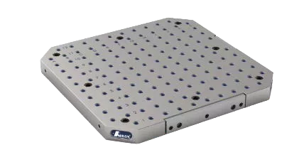
AMROK, a division of AME, is one of the largest and most well-known suppliers of fixture plates, also known as grid plates. The tombstone suppliers listed previously supply fixturing plates as well. A typical AMROK fixture plate is shown below. It is designed to be attached to the work table or face of a tombstone, and is provided with a grid of precisely located hardened bushings over tapped holes. Precision dowels can be placed in the bushings and used as stops for locating workpieces. Obviously, the positional accuracy of the holes on the plate is an important consideration when comparing products.
Summary: Tombstones & FIxture Plates
Part 10: Trunnion Systems & Rotary Tables
This article is primarily aimed at users of three axis machining centers, whether vertical (VMC) or horizontal (HMC). These types of machines are restricted to fixturing and machining parts on a single side of a tombstone or fixture plate. As previously mentioned, one key to reduced cycle time and improved productivity is to maximize the number of parts that can be fixtured simultaneously. This practice enables a dramatic reduction in the number of tool changes required per part, since the same operation can be carried out on all workpieces in the fixture before changing to the next tool. It also can lead to more efficiency and less time spent loading and unloading parts. For cases where the parts being machined are substantially smaller than the workspace of the machine, the addition of a rotary table or trunnion system can enable parts to be fixtured on multiple sides of a tombstone. This can lead to significant reductions in cycle time and increased profitability. To accomplish this, it isn’t necessary to scrap your three-axis machine in favor of a four or five axis model. Instead, it is often possible to add on an aftermarket rotary table or trunnion system.
These devices are available as true fourth axes, capable of active positioning and contouring during machining. They are also available as pure indexing systems, with their position locked during machining and while other machine axes are in motion. These types of systems are normally used in a “3 + 1” mode where the indexing axis and workpiece is brought into the desired position and locked; followed by conventional 3-axis machining. It should be noted that, in addition to allowing parts fixtured on multiple sides of a tombstone to be accessed, such systems also can enable more complex parts to be machined with a nominally three-axis machine. For instance, suppose you have a part with two surfaces at 45 degrees to each other, and holes to be drilled into these surfaces. The use of an auxiliary indexing axis can enable all of these features to be machined without refixturing the part.
Compound systems with two rotary axes are also available to convert a 3-axis machine into a true 5-axis machine. When selecting a trunnion or rotary table, there are some important considerations to keep in mind.
If the auxiliary axis system is used to index new sides of the tombstone into position for machining, the indexing accuracy of the system is important. Consider a tombstone that is 12 inches in width. When it is rotated, an error of less than 0.005 degrees will cause a 0.001 inch error on the parallelism of the new face to the machine’s axis of motion. Therefore, unless your tombstones are very narrow, look for indexing accuracy of better than 0.001 degrees, or about three arc-seconds.
Most rotary axis positioning systems make use of a gear drive to connect the drive motor to the rotating table; normally a worm gear drive, or a spur or bevel gear drive. Gear drives are susceptible to backlash, or reversal errors, unless manufactured with exceptional accuracy or designed with special antibacklash features. Worm gear drives have very high speed ratios, which can make it difficult to achieve high speed motion of the table. They also tend to generate a lot of heat from the sliding motion of the worm face on the worm wheel, which can be detrimental to accuracy. Spur and bevel gear drives can enable higher speeds, but are susceptible to backlash unless the center distance between the gears is controlled to a very high degree of precision, or other antibacklash features are designed into the drive.
For these reasons, it will usually be preferable to select rotary tables where the position feedback system, or encoder, reads directly on the table, rather than on the drive motor. This will not prevent backlash or reversal errors, but any unwanted motions will be sensed by the feedback system and communicated to the controller. It will also negate any positioning errors arising from small irregularities in the pitch of the drive gears.
The ability to index accurately is of little value if the machining forces cause the angular position of the axis to vary. For this reason, some indexing systems have auxiliary brakes that automatically engage to hold the axis in position. For these types of systems, the brake holding force must be sufficient so normal machining forces do not cause slippage. Other indexing systems are designed with special couplings that only permit 40 engagement in a finite number of discrete positions. These systems have the advantage that they do not require a brake to hold position. Their disadvantage is that they are limited to discrete angular motions, and if you need to index to an intermediate angular position you will not be able to.
As mentioned earlier, it is good to think of your machine tool as a chain of stiff springs connecting the tool tip to the workpiece. Whenever another element, such as a trunnion or rotary table, is introduced to the machine, it is absolutely true that the composite system becomes less stiff. While this cannot be avoided, it can be managed by making sure to select the systems with the highest stiffness available. This can be difficult since most manufacturers do not provide stiffness information in their specifications. However, it is possible to perform a simple experiment to see whether the new device meaningfully compromises the capability of your machine. To perform the experiment carry out the following steps:
- Clamp a flat piece of metal in your machine using your current system. Using an endmill with a stick-out length of 3 to 4 times the diameter, take a succession of short parallel slotting cuts in the metal using the feeds and speeds you would normally use. With each new cut, increase the axial depth of the cut until chatter occurs. The limiting stable axial depth of cut is dependent on the effective composite stiffness acting between the tool tip and part.
- Now use the indexing system. Clamp the same piece or type of metal onto the indexing system, and repeat the cutting tests above using the same tool, stickout length, feeds, and speeds. If the limiting stable axial depth of cut is unchanged, the addition of the indexing system did not make a meaningful change in the total machine stiffness. In most cases, you will find that the limiting axial depth has decreased. If the change is minimal, then the indexing system may not have much effect on the ability to aggressively machine parts. However, if the addition of the indexing system makes a big change, then you must either accept that its use may dramatically limit your ability to achieve material removal rates, or you must look for a stiffer alternative.
The productivity advantages of adding a trunnion or rotary table can be largely negated if the indexing has to be done manually. Ideally, the indexing action can be commanded directly from the CNC part program. Most manufacturers of indexing systems try to make sure their products are compatible with major machine controllers. However, you should check to see that your controller and version are supported, and understand the steps needed to complete the integration.
The addition of a 4th axis to your machine will consume a significant fraction of your machine’s workspace. Additionally, for some systems, the motion of the rotary axis can create interference problems with the spindle nose and housing, and potentially other parts of the machine. It is important to fully understand these effects prior to selecting a rotary table or trunnion system.
Trunnion Systems
Trunnion systems are generally intended for use with three-axis VMCs. Although they could also be mounted on the face of a tombstone in an HMC, it would generally be preferable to use a rotary table under the tombstone.
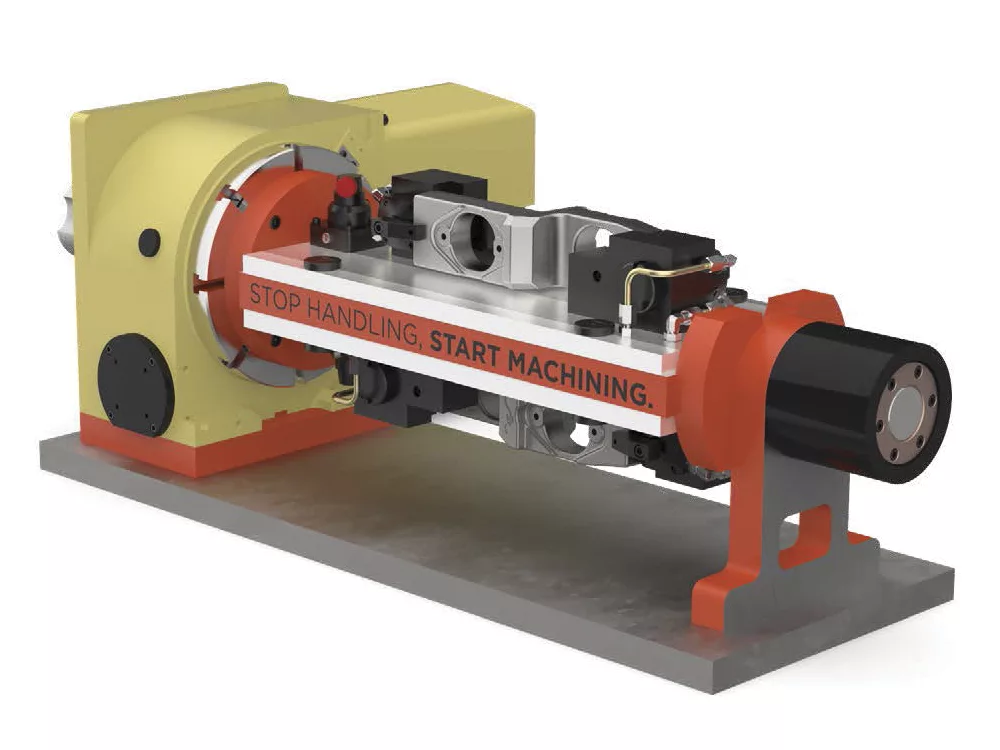
One of the best-known suppliers of trunnion systems is Martin Trunnion. They supply a wide variety of sizes and configurations designed to accommodate almost any need. Their products are designed to have one end directly mounted to a CNC rotary table supplied by one of a number of manufacturers. They also offer external braking systems to ensure that their trunnions remain firmly in position during machining. Martin offers a number of tombstone geometries to fit on their trunnion tables, thus offering flexibility to accommodate a wide variety of part sizes and shapes. Their tombstones are compatible with the clamping systems from a number of well-known third party manufacturers.
Rotary Tables
Rotary tables can greatly extend the capability and productivity of 3-axis HMCs by allowing the conventional tombstone to be replaced with a multi-sided one, and using the rotary table to bring each side into position for machining the parts mounted on it. This can greatly increase the number of parts that can be fixtured simultaneously, decreasing cycle time and increasing productivity.
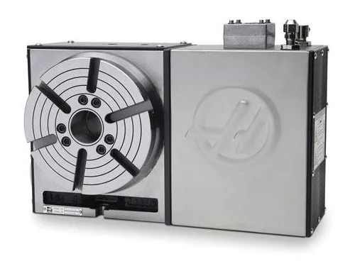
CNC rotary tables are available from a number of different manufacturers, including Haas, Nikken, Koma, and Samchully. Haas Automation Inc., offers a complete line of aftermarket CNC rotary tables and indexers suitable to a wide range of machine sizes. While they are designed to be compatible with Haas CNC machine tools, they are also usable with most other major brands of CNC machines.
Koma Precision Incorporated is a Japanese company that produces a full line of rotary 4th and 5th axis rotary tables. In addition to the normal worm gear drive units, they also offer two other drive modes. The first is a novel balldrive system designed for high-speed operation and zero backlash. The second is a direct drive system where the rotor of the drive motor is directly connected to the rotary table. Obviously this will enable very high speed motions, but also means that the drive motor must have high torque, since the machining and other forces are directly seen by the motor.
Nikken is another Japanese producer of a full line of rotary axis products. They offer worm drives with carbide screws and ion-nitrided hardened worm wheels for optimum performance and durability. Korean company Samchully offers a full range of types and sizes of CNC rotary tables. Their products feature auxiliary clamping systems that can be either hydraulic or pneumatic, offering very high clamping forces to resist heavy machining.
Summary: Trunnion & Rotary Tables
The addition of a rotary axis to a 3-axis machine, whether indexing or full CNC contouring, can be a powerful tool for increasing productivity in series or batch production. It can enable parts to be mounted on multiple sides of a tombstone, and also enable machining of multiple sides of a part without refixturing. A wide range of products suitable to virtually any machine size and type is available from a selection of manufacturers.
Part 11: Modular Workholding Systems
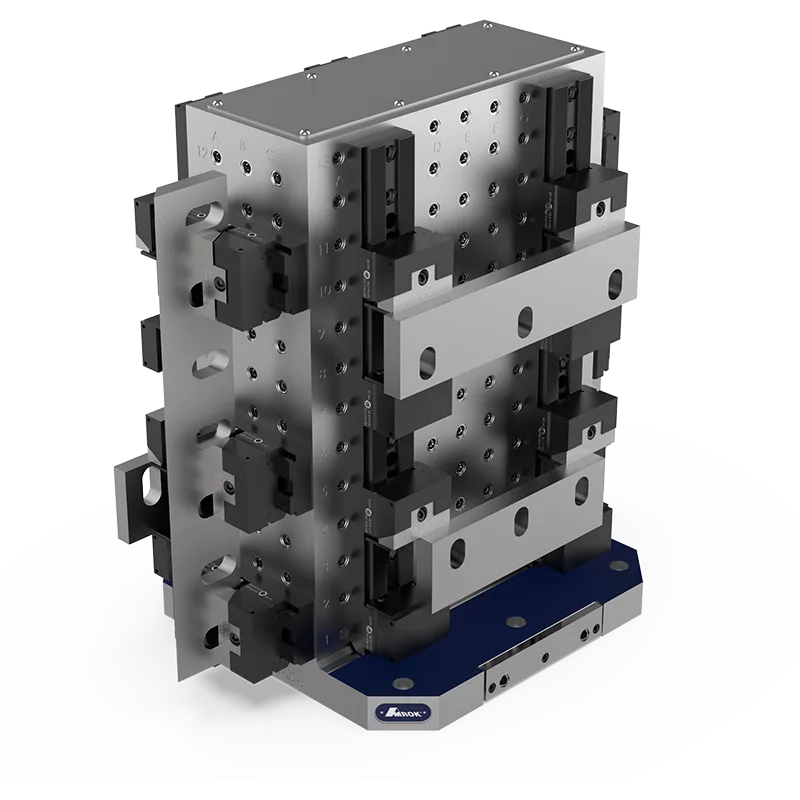
Once you have selected your tombstone, and possibly an auxiliary axis system, it’s time to address the question of how you will actually attach the workpieces to the tombstone surface. Once again, the goal is to increase both productivity and quality. Productivity is improved by reducing setup time, part change time, tool change time, etc. If you have very large production runs and batch sizes, it can make economic sense to custom design the workholding system to maximize productivity for one particular part. However, it is much more common to have a broader mix of parts to be produced on the same machine. In this scenario, you will almost certainly want to use locating and clamping components that can be easily reconfigured to accommodate the widest range of part sizes and shapes. Modular workholding systems can meet this need.
In this article, we will look at modular rail systems that are used to enable rapid and precise relocation of a wide variety of clamping elements on the tombstone surface, enabling the flexibility to quickly reconfigure your workholding system to hold a wide variety of workpieces.
MODULAR RAIL SYSTEMS
Modular rail systems are designed to be more or less permanently mounted to the surfaces of the tombstone.
They are often designed to be compatible with the standard 2-inch grid of locating holes found on many
tombstones. The rails normally have at least one face with precision serrations along their length, and features on other faces that enable clamping and locating elements to be easily and securely fastened to the rail. Compatible clamping and locating elements will also have serrated surfaces that mate with the rails, allowing the individual elements to be quickly and precisely relocated to known locations, and enabling the clamping of different sized workpieces. This eliminates the need for laborious and time-consuming indicating of the clamping elements into alignment or touching-off of surfaces to establish location.
Also, because the clamping elements can be moved in increments of the pitch of the serrations (typically around two millimeters), the clamping device itself only needs to have a range of motion of a little more than the serration pitch. This short range of motion for tightening and loosening can help to minimize part change times. The figure below shows a typical setup with rails mounted on four sides of a tombstone, and clamping and locating elements mounted to the rails to enable four parts to be held on each side.
When selecting a modular rail system, it is important to consider the following factors that may affect their performance:
- Accuracy: The straightness of the rails and the precision of the serrations will directly impact the tolerances you are able to hold while using these systems, since the serrations and rail surfaces align the part to the machine’s coordinate axes and locate the part within the machine’s workspace. The goal of using these systems is to avoid the need for indicating and touching off when the system is reconfigured. This can only be achieved when the rail system components are accurate.
- Durability: Ideally, all surfaces that align and locate the clamping elements should be hardened to prevent wear or damage that could affect their precision.
- Ease of Cleaning: Machine shops are outstanding producers of small, hard particles. When such particles collect on the rail and mating component surfaces, they can affect positioning, potentially causing significant dimensional errors on the parts. All of the critical surfaces should be easy to inspect and clean.
- Clamping Force: Heavy cuts in hard materials can create large machining forces. Make sure that the system you are considering is capable of creating clamping forces high enough to resist these forces.
- Stiffness: The rails and the components that mount on them are elements in the flexible chain that runs from the tool tip to the part, and they will inevitably lower the composite stiffness of the system. If they are too flexible, it may impact how aggressively you can machine, and the tolerances you can hold. This effect can be difficult to quantify without specialized instrumentation, but you can see if it is significant by comparing the limiting, stable axial depth of cut in a slotting cut for a workpiece mounted directly to the face of the tombstone, and the same workpiece held in the modular rail system. If the difference is very small, then the modular rail system does not significantly impact the composite stiffness of the machine.
- Compatibility: Before selecting a modular rail system, it is important to consider the range of clamping elements you want to use. Make sure that the rail system is compatible with them.
Triag and Schunk are well-known suppliers of modular rail systems for workholding. The Triag modular powerCLAMP™ system has several unique features. The rails have serrations with a 2 mm pitch, and the two serrated sections have no T-slot type features between them that can easily catch chips and may be hard to clean. The clamping elements mount vertically onto the rails, so that they can be removed and replaced without disturbing other elements along the rail, and are designed to be clamped with a single screw that can be accessed from either side of the rail, enabling rails to be mounted close together. Standard rails are available in lengths ranging from 90 mm to 850 mm. Triag offers over 200 different variants of clamping modules to mount on the rails, and over 120 different jaws to mount on those modules; making it possible to design systems to accommodate virtually any workpiece shape or size. Their clamping modules can provide clamping forces up to more than 6000 lbs, making them suitable for heavy machining applications. They also offer monoblocks and towers with serrations on multiple sides for 5-axis machining.
Schunk offers the KSM2 modular rail system, produced by Gressel Spantechnik in Germany. A typical setup is shown below.
The rails use a deep T-slot to attach the clamping elements. However, unlike typical T-slots, the clamping elements are installed and removed from above, not slid in from the ends, allowing individual clamps to be removed or adjusted without disturbing others on the rail. Tightening of the clamping elements to the rail is also done from above, so the rails can be placed in close proximity. The rails come with a laser-etched ruler on the sides, enabling quick and easy placement of the clamps on the rail. A wide variety of jaws are available to accommodate workpieces of different sizes and shapes.
Summary: Modular Workholding Systems
Part 12: Getting A Grip
When friction isn't enough.
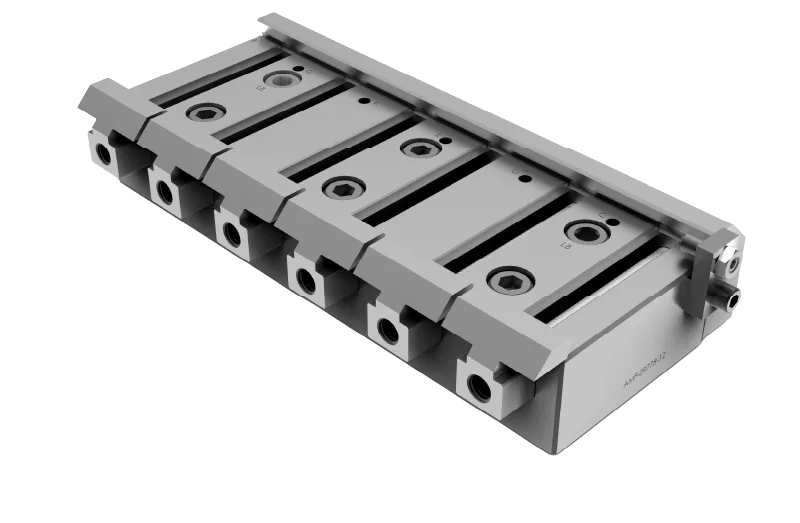
One of the tradeoffs in workpiece fixturing is between clamping the part securely and the desire to leave as much of the surface of the workpiece as possible unobstructed. The rise in five-axis machining has highlighted this problem since these machines make it possible to bring five sides of the workpiece into position for machining, unless the workholding system blocks access. Machining cost can rise dramatically when parts need to be refixtured to access additional faces, due to the time required to remove and reclamp the part. This is especially true when a whole new fixturing setup has to be created for the new part orientations, which is most often the case.
To avoid this and enable five-sided machining, it is not uncommon to try to clamp a part just along its lower edge. Edge clamping can work, but it is all too common for the part to be ripped from the clamp by the machining forces, with potentially disastrous results. Let’s look at the reasons why edge clamping can be a risky strategy, and explore alternatives that rely on mechanical interference to secure the part instead of friction
THE RISKS OF EDGE CLAMPING
The primary risk of edge clamping is that the part can be pulled out of the clamp jaws and thrown violently around the machine enclosure. When this occurs it virtually always entails a significant disruption to the flow of production. At minimum, to ensure subsequent parts will be in-tolerance, the existing fixture will need to be trammed and indicated to make sure it is still aligned with the machine axes, and has not moved relative to the machine origin. The tooling offsets will also need to be checked. This can lead to interruptions ranging from minutes to hours, depending on the availability of persons with the necessary skills to perform the checks.
In many cases it will be found that the fixture has moved unacceptably due to the violent action of the part being ripped from the clamps. When this occurs, the complete fixturing setup will need to be torn down, and essentially rebuilt from scratch. All of the tooling offsets will need to be redone. In many shops, only a few highly skilled individuals have the ability to perform this task, potentially meaning that the affected machine can be idled for hours or even days while waiting to be serviced.
In the worst case scenario, the part is thrown violently around the machine enclosure, potentially damaging the machine itself or the fixturing components, breaking the tools, and even being ejected through the viewing ports of the enclosure, which generally aren’t designed to withstand these types of ballistic events, and endangering shop personnel.
WHY EDGE CLAMPING CAN BE DIFFICULT
Edge clamping occurs when you try to hold a workpiece along its edges, thereby leaving more surface of the part available to be machined. The figure shows a schematic of this situation.
Here, the blue workpiece has a height, h, width, w, and the vice jaws engage the part with a grip length, g. The vice jaws exert a clamping force, F_clamp, on the part; and we will assume a machining force, F_machining, is exerted along the top edge, as it would be if the top surface was being machined flat. Edge clamping occurs when the grip length, g, is very small compared to the part width, w, i.e. when the ratio of w/g is greater than around 100. For example, if the part width is 400 mm, a clamping grip length of 4 mm or less would be considered risky edge clamping. There are two reasons why this clamping arrangement is risky. The first is force multiplication, and the second has to do with the amount of interference keeping the part from tilting out of the jaws.
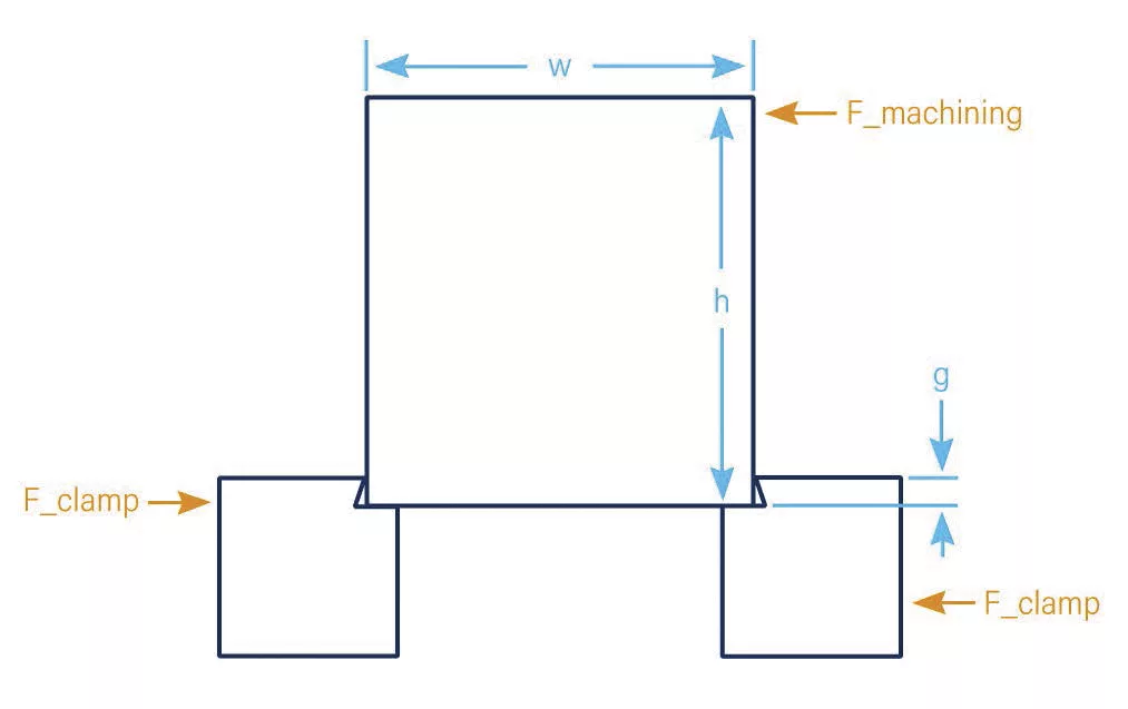
Force multiplication occurs when the height of the workpiece is significantly larger than the width. In the figure below, the right-hand vice jaw is hidden and only the forces it exerts on the part are shown. The clamping force is transmitted directly to the part, and it creates a frictional force that resists the tendency of the machining force to rotate the part about corner A, and up and out of the jaws. In order to do this, the friction force must be at least, . The frictional force is limited to a small fraction of the clamping force, and it is unwise to count on it being more than about 25% of the clamping force.
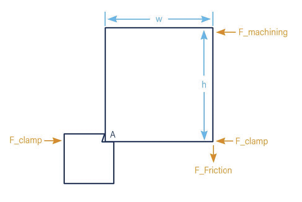
Therefore, if the part has a width of 400 mm and a height of 800 mm, the clamping force will need to be about 8 times the machining force to assure adequate friction. For heavy cuts, the machining force can easily exceed 500 lbs or more, meaning that a clamping force of over 4000 lbs is needed. This is difficult to achieve with manual screw operated vises, or to assure in a production environment when the machine operator is expected to clamp and unclamp dozens of parts a day or more. A single failure to adequately torque the clamping screw can result in the part being pulled out of the jaws, with the consequences that entails. And, as we will see below, even with adequate clamping force, the part may still pull out of the vise.
The second reason why edge clamping is difficult has to do with the minimal amount of mechanical interference it creates. The figure below shows the part being tilted out of the vise jaws by the machining force. The part is tilting around the upper corner of the left vise jaw, A, and the lower right corner of the part, B, must clear the other vise jaw in order to come free. The distance, d, between points A and B on the part is only slightly larger than the width of the part, and the distance between the jaws. For example, if the part width is 400 mmm, and the grip length of the jaws is 2 mm, the distance, d, is only 400.005 mm, or 5 micrometers more than the width of the part.
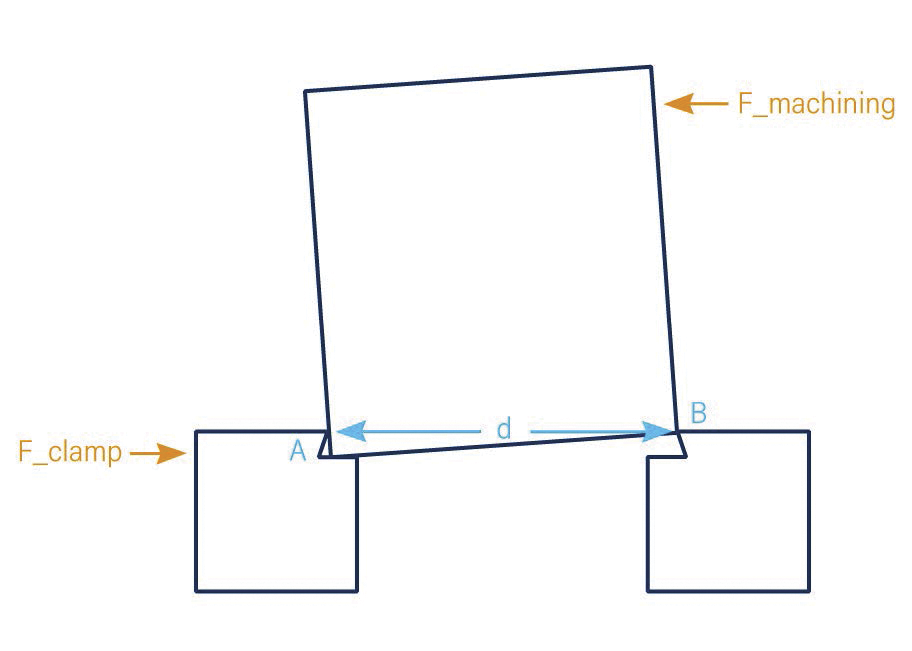
That means that the corner of the vice only needs to penetrate 5 micrometers into the part surface in order for the lower right corner of the part to clear the vise and come free. The amount of force required for the vise corner to create this penetration is generally fairly small, and the machining force may be sufficient to cause it. This situation will occur in virtually all edge clamping situations where the ratio of the part width to the grip length is large, and it often leads to loss of clamping and parts being torn from the fixture.
What's The Solution?
The benefits of edge clamping in terms of productivity gains can be significant, so of course creative engineers and machinists have come up with solutions that maintain the benefits with only a few drawbacks. The solution is to redesign the region where edge clamping occurs to create additional mechanical interference, eliminating the tilt-out problem and reducing the dependence on friction to restrain the part. There are two main strategies commercially available to achieve this. The first relies on dovetail features, and the second relies on mechanically indenting the part with a pattern that matches a mating pattern on the vise jaws.
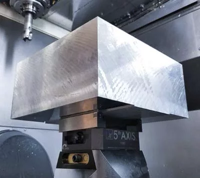
A number of suppliers offer dovetail clamping solutions. However, 5th Axis Inc. has a particularly well thought out range of offerings for dovetail clamping. The figure above shows a typical setup. Notice that the workpiece is substantially larger than the clamp itself, allowing full 5-sided machining.
Advantages of dovetail clamping include:
- Excellent workpiece stability with virtually no risk of loss of grip or dependence on high clamping pressure
- Usable on virtually any type of workpiece material
- Great part location, since clamping is always to a precision machined surface
Disadvantages of dovetail clamping include:
- Creating the dovetails requires an additional machining process operation, partially negating the advantages of improved part access. However, the dovetail cutting operation is simple and fairly rapid, and some material suppliers now offer stock with precut dovetails.
An alternative to reduce the reliance on friction and to create mechanical interlocking is to indent features on the part that mate with features on the vise jaws. This strategy has long been recognized, and virtually all vice manufacturers offer jaws with knurled patterns designed to “dig into” the part to create mechanical interference. The limitation of this strategy is that conventional manually operated vises are limited in the force they can apply, typically a few thousand pounds maximum; and this force may be inadequate to sufficiently deform the workpiece, particularly if the clamp area is large or the workpiece material has medium to high hardness.
Lang Technologies overcomes this limitation by offering a portable, hydraulic unit to prestamp features into the part that mate with corresponding features on their vise jaws. The portable hydraulic unit can create forces much higher than any manual screw-operated device, so it is applicable to much harder materials. The figure below shows the stamping unit and the accompanying Makro-Grip vise. The stamping unit provides quick indenting of the part without tying up valuable machining center time.
Advantages of the pre-stamping method include:
- Secure clamping that does not rely solely on grip pressure to hold the part
- A rapid process for creation of the clamping features without the need for an additional machining operation
- Repeatable location of parts since the indented features mate with complementary features on the vise jaws
- Capability of very thin edge grips
Disadvantages of the pre-stamping method include:
- Pre-stamping is not applicable to very hard materials since the forces required to plastically deform these materials are extremely high, and require die jaws of even higher hardness. Lang recommends use on materials softer than HRC35, although they do offer a higher capacity unit for materials up to HRC45.
- With pre-stamping the clamp jaws will always cover a small portion of the sides of the workpiece, precluding full fivesided machining. This can be overcome by machining a boss onto the base of the part for clamping, although this option eliminates much of the convenience of the pre-stamping process.
Summary: Why Edge Clamping Can Be Difficult
Part 13: Workholding Without Clamping
Almost all workholding strategies involve applying relatively large clamping forces to the part to generate sufficient friction to resist the machining forces. Of course with these systems, part motions in some directions are impeded by mechanical interference with vice jaws or other elements of the clamping system; but in most cases there are some directions that rely on friction to restrict part movement. However, in situations where the part is thin, fragile, or flexible, the clamping forces needed to restrain it may damage the workpiece or deform it so much that tolerances are compromised. In this article we will look at several methods for holding the workpiece by essentially “adhering” one, normally flat, surface to the fixture. These “face fixturing” methods include vacuum systems, magnetic clamping, freezing, and glues or other adhesives. We will discuss how each method works, and any limitations or cautions for its use.
LIMITED HOLDING FORCE
All of the methods for face fixturing provide limited holding force, and in general the force level is directly proportional to the area in contact. Therefore, for very small parts the holding force will often be quite small. As the contact area gets larger, the force increases rapidly. For example, the holding force for a 2” X 2” contact area will be eight times larger than for a 1” X 1” area. A 3” X 3” contact area will generate 27 times the force of a 1” X 1” area. For this reason, unless the contact area is quite large, face fixturing is generally limited to light cuts to ensure that the cutting forces are fairly small. Face fixturing is generally not used for heavy, roughing cuts.
AVOID TALL PARTS
Face fixturing should only be used when the height of the part is a small fraction of the smallest base dimension, generally less than 50% is desired. The reason for this is that when the cutting force is applied to the top of a “tall” part, high tensile stresses are generated at one side of the interface; and these can easily exceed the limiting value for the fixturing method. When this occurs, a sudden loss of adhesion occurs and the part can be thrown violently from the machine.
PART LOCATION
Most face fixturing systems do not naturally include mechanical stops to ensure the parts are accurately oriented to the machine coordinate system, or located at a known point. To be sure, it is almost always possible to design and fabricate auxiliary systems to locate the parts, but this requires extra time and expense.
WORKPIECE PREPARATION
For some face fixturing systems, the attachment face of the workpiece must be very flat and smooth in order for the expected attachment force to be reached. This is particularly true for vacuum systems and to a lesser extent for magnetic systems. This means that often an additional operation will be needed to prepare the workpiece before it can be fixtured and machined.
AUXILIARY SYSTEMS
Most face fixturing technologies will require some sort of auxiliary equipment to be added to the machine tool, such as vacuum pumps, freezers, and UV light for curing adhesive. This, of course, incurs additional expense and may require expert installation if it is to be fully integrated with the CNC controller.
Magnetic clamping methods have been in existence since before the advent of CNC technology, and are routinely found on surface grinders for example. Magnetic systems are capable of generating very high holding forces, depending on the strength of the magnets used, and the magnetic properties of the workpiece. Over the past decade or so, the introduction of “rare earth” permanent magnets has enabled a substantial increase in the achievable holding force. Naturally, magnetic systems are generally limited to use with ferrous materials.
Most magnetic holding systems use permanent magnets to grip the part. Electromagnets are an option but suffer from two drawbacks. First, they require continuous electrical current to flow to generate the magnetic force, and this current will tend to heat up the magnet; potentially leading to part dimensional errors due to thermal expansion. Second, they are always at risk of instantaneous loss of holding power if there is any interruption in the flow of electricity, and thus present a safety hazard.
Of course, with permanent magnet systems there must be a way to turn off the magnet in order to load the part in a controlled manner and also to release it. There are two main methods to accomplish this. The first uses a rotating switch. This rotates an internal magnet in the system 90 degrees so that its polarity is no longer aligned with the “magnetic circuit” that is created when the part is loaded, thus reducing the magnetic attraction to a very small level. Virtually every machinist is familiar with the magnetic bases used to hold indicators, and they all work on this principle. Magnetic vises are simply larger versions of this. An advantage of permanent magnet chucks is that no auxiliary systems are required. A disadvantage is that switching from “on” to “off” is necessarily a manual process, making it difficult to fully automate the loading/ unloading process.
Another way to turn off the magnets is to install an electromagnet in the system whose field is opposite of the permanent magnet field and thus neutralizes it. This has the advantage of being normally on, so loss of power will not compromise the workholding capability.
There are numerous suppliers of magnetic chucks. For example, Magnetic Products Inc. offers a broad line of products. Their rare earth permanent magnet chucks can provide holding forces up to 232 lb/in^2 of contact area, while their electro-permanent magnet chucks can provide up to 247 lb/in^2 of holding force. This is the force that pulls the part down onto the surface of the chuck. Machining forces are generally perpendicular to the attraction force, and therefore must be resisted by friction between the workpiece and the chuck face. The amount of friction that can be generated between two surfaces is highly dependent on the materials in contact, their surface finish, and other factors. In general, it is not wise to count on the frictional force to be more than about 20% to 25% of the attractive force. With these chucks, a 2” X 2” workpiece could potentially withstand machining forces up to around 250 lbs; an amount that could be easily exceeded in heavy cuts.
Vacuum chucks work by mounting a surface of the part against the chuck face that has numerous small holes or channels connected to an external vacuum pump. When the part is brought into contact with the surface, the area under the part is subject to vacuum, and the other surfaces of the part are subject to atmospheric pressure, which presses the part against the chuck surface. The normal atmospheric pressure is around 14.7 lbs/in^2, which limits the maximum force that can be achieved.
In practice, the “holding force” is often limited to about 10 lbs/in^2. This means that a 2” X 2” part would have a downward force of around 40 lbs. Friction could only provide about 10 pounds of force to resist machining forces, an amount which will be exceeded by almost any machining operation unless the material being machined is very soft. For this reason, vacuum chucks often use auxiliary stops on the surface of the chuck that serve to both locate the part, and to resist machining forces. The caution against tall parts is particularly true for vacuum systems since once the part starts to tilt under machining forces, the vacuum will be lost, and the part will be thrown from the chuck.
Triag offers a full line of vacuum chucks, including external vacuum pumps, and silicone sealing cord to ensure the best possible seal between the chuck surface and the part. According to Triag, their vacuum chucks are particularly suited to large surface, thin-walled, and non-magnetic workpieces.
Another alternative to magnetic and vacuum systems is the introduction of an aqueous gel between the part and the chuck surface which is then chilled to freeze, and adhere the part to the chuck surface. Triag offers complete systems for this type of clamping, including the refrigerating unit to supply cold gas through channels in the chuck to lower its temperature to -8 C; and also to quickly heat it up to release the part. They claim adhesion forces up to 290 lb/in^2, but warn that shock forces must be avoided as the ice film fails by brittle fracture; meaning that the part can become detached from the chuck if impact forces are applied.
Drawbacks of freeze clamping include the auxiliary equipment required to freeze and thaw the interface, and the time, up to 60 secs, required for the clamping and release to take effect. Another potential issue with freeze clamping is the effect of thermally induced deformations of the part. For example, aluminum has a coefficient of thermal expansion of around 13 ppm/degree fahrenheit. Therefore, an aluminum part 10 inches long will shrink by over 0.006 inches when its temperature is reduced from normal room temperatures to -8 C. This may cause tolerances to be violated when the part is machined at these temperatures.
Another alternative is to use adhesives to bind the workpiece to the worktable surface. One can find examples of the use of double sided tape, super glue, and other adhesives to secure the workpiece for machining. For example, Blue Photon uses a UV curable adhesive to hold workpieces in place. In this system, a fixture consists of multiple small pads that are arranged to conform to the workpiece surface, making it compatible with irregular-shaped workpieces. Each pad is supplied with a UV light source that can quickly cure the adhesive. In use, UV curable adhesive is applied to the surfaces of the pads and the workpiece is brought into contact. Once the workpiece is in the correct position, UV light is applied to the adhesive, causing it to polymerize and harden, adhering the part to the fixture. This provides a strong bond between the workpiece and the fixture. Obviously, the actual strength of the attachment is dependent on the number of pads, and the properties of the adhesive, but strengths up to several hundred pounds per pad are claimed at typical machining temperatures. Blue Photon also supplies a complete array of post-machining baths and equipment to remove the part from the fixture and remove all adhesive from the surfaces.
Adhesive clamping is not currently a widely used practice. However, for irregularly shaped and delicate workpieces it can provide a viable solution. The time required for bonding and debonding the workpiece makes this an unlikely candidate for high-volume production unless the workpiece geometry is so irregular that more conventional fixturing methods are not viable. Additively manufactured parts needing finish machining may benefit from adhesive clamping since their surface finish is often quite rough, and they may have complex geometries.